Зеркальное отображение базы данных (sql server)database mirroring (sql server)
Содержание:
- Размышления
- Конфигурация зеркального отображения портов HP
- Список оборудования:
- HP Switch Book
- HP Switch Playlist:
- Связанный учебник HP Switch:
- Учебное пособие — Конфигурация зеркального отображения портов HP
- Учебник — мониторинг порта коммутатора
- Port mirroring with a switch
- About port mirroring
- Switches vs Hubs
- Создание RAID-массива или Зеркалирование дисков в новейшей Windows 10 Fall Creators Update
- Basic RSPAN configuration
- Set up SPAN on CatOS switches
- Types of SPAN:
- Basic SPAN configuration
- Зеркальная Windows
- Зеркалирование Windows: что это
- Paessler Packet Capture Tool
- Configuration
- Encapsulated Remote SPAN (ERSPAN)
- Switches and hubs
- Port mirroring with a hub
Размышления
Раз дополнительный шлюз ставить нельзя, значит пускать трафик через какое-либо устройство тоже не вариант – придётся работать с копией трафика. А то, что нужна детализация в том числе по DNS-именам сайтов, к которым идёт обращение, делает неприемлемым использование NetFlow и Ulog из предыдущей статьи. На счастье ядром сети является Cisco Catalyst 3550, значит можно попробовать снять копию трафика (зеркалирование) и анализировать уже её.
В общем виде сеть выглядит так:
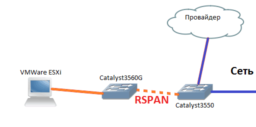
Вся основная сеть не показана (она в правой части). Я решил снять копию трафика с порта, ведущего к провайдеру и послать его на виртуальный сервер через ещё один коммутатор Catalyst3560G, по счастливой случайности оказавшийся возле сервера виртуализации.
Конфигурация зеркального отображения портов HP
Хотели бы вы узнать, как настроить функцию зеркального отображения портов на коммутаторе HP с помощью веб-интерфейса вместо использования командной строки? В этом уроке мы расскажем вам все шаги, необходимые для настройки функции зеркального отображения портов на коммутаторе HP 1910, 1920 или 5500 с использованием веб-интерфейса.
Список оборудования:
В следующем разделе представлен список оборудования, используемого для создания этого руководства для коммутатора HP.
Все перечисленные выше аппаратные средства можно найти на веб-сайте Amazon.
HP Switch Book
Наша книга находится на веб-сайте Amazon — English | Portuguese | Spanish
Несмотря на хорошие знания, связанные с компьютерными сетями, и даже некоторые сертификаты по этому вопросу, Люк, 26-летний ИТ-аналитик только что получил миссию по развертыванию новой сети, используя только коммутаторы HP.

Следуйте за историей Люка и поэтапным подходом к реализации сетевого проекта, созданного сертифицированным специалистом по управлению проектами.
HP Switch Playlist:
На этой странице мы предлагаем быстрый доступ к списку видеороликов, связанных с коммутатором HP.
Playlist
Не забудьте подписаться на наш канал YouTube, названный FKIT.
Связанный учебник HP Switch:
На этой странице мы предлагаем быстрый доступ к списку руководств, связанных с коммутатором HP.
Список учебных пособий
Учебное пособие — Конфигурация зеркального отображения портов HP
Откройте программное обеспечение браузера, введите IP-адрес коммутатора и войдите в веб-интерфейс коммутатора HP Switch.
На экране приглашения введите регистрационную информацию администратора.
Информация о доступе к заводским настройкам:
• Имя пользователя: admin
• Пароль: (без пароля)
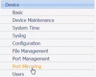
После успешного входа в систему будет отображено административное меню.
Откройте меню «Устройство» и выберите параметр «Зеркалирование портов».
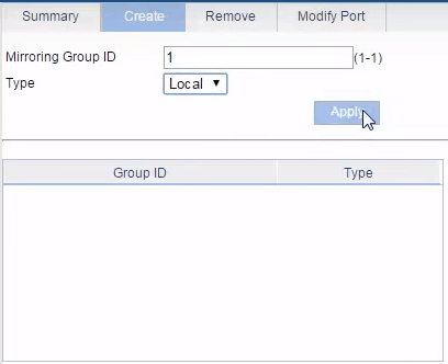
На экране «Зеркалирование портов» выберите вкладку «Создать» в верхней части экрана.
Введите желаемый идентификационный номер, выберите тип «Локальный» и нажмите кнопку «Создать».
• Идентификатор группы зеркального отображения: 1
• Тип: местный
Теперь вам нужно решить, какой порт коммутатора должен отвечать за мониторинг сетевого подключения.
Перейдите на вкладку «Изменить» и выполните следующую конфигурацию:
• Группа контроля: 1
• Тип порта: Порт монитора
• Порт переключения: порт1
После завершения настройки нажмите кнопку «Применить».

Затем вам нужно решить, какой порт коммутатора должен контролироваться.
Перейдите на вкладку «Изменить» и выполните следующую конфигурацию:
• Группа контроля: 1
• Тип порта: зеркальный порт
• Ориентация потока: обе
• Порт переключения: Port2
После завершения настройки нажмите кнопку «Применить».

Вы успешно настроили зеркалирование портов коммутатора.
Не забудьте сохранить конфигурацию коммутатора.
Учебник — мониторинг порта коммутатора
После завершения настройки коммутатора вы, вероятно, захотите следить за тем, чтобы сетевой трафик шел и шел из рабочей станции.
На компьютере под управлением Windows вам необходимо загрузить и установить программное обеспечение сетевого мониторинга, такое как WIRESHARK.
Подключите компьютер, работающий от WIRESHARK, к порту коммутатора 01.
Запустите приложение WIRESHARK на компьютере, подключенном к порту коммутатора 01.
Подключите компьютер, который вы хотите контролировать, на порту коммутатора 02.
Программное обеспечение WIRESHARK автоматически обнаружит все сетевые пакеты, отправленные или полученные компьютером, подключенным к порту коммутатора 02.
2018-07-25T23:43:30-03:00
Port mirroring with a switch
When a switch receives a packet, it references the destination address in the header of the datagram. It then makes a copy of the packet and sends that new version out on the port number that it has associated with that MAC address.
In standard operations, which is termed “unicast,” only one copy is made of an incoming message and that is sent out only on one port. Switches are capable of duplicating traffic, however. For example, when the switch receives a broadcast message, it makes the same number of copies as its count of active ports and sends one copy out on each of those ports. Switches also have “multicast” capabilities, which require them to create a limited number of copies.
As all switches are programmed with the ability to handle broadcast and multicast messages, the task of duplicating packets does not present their hardware with a problem. Conceptually, getting your switch to perform packet duplication requires very few tasks:
- The switch is instructed to make a copy of all traffic.
- The switch sends all traffic onto its intended destination.
- The switch sends a copy of all traffic to a nominated port.
- You collect all traffic at the nominated port.
Getting all packets duplicated travelling through a switch is a very simple job and doesn’t use up very much extra processing effort on the part of the device. If you want to examine the packets travelling through a specific switch, you just need to tell it to duplicate all of that traffic and send it to a port and also tell it to associate the MAC address of your computer with that designated port number. You then need to put your computer’s network card into promiscuous mode to ensure that it will pick up all traffic and not just those datagrams with its MAC address on them.
About port mirroring
Port mirroring offers a method of duplicating network traffic and directing the copy towards a data store. In a splitter, you use a device that duplicates all traffic with one copy continuing to its intended destinations and the other showing on a screen or going to a file. With port mirroring, you use exactly the same technique, but you alter the settings of your switch to create a data duplication function, thus removing the need to install a separate physical device.
Essentially, a port mirroring instruction tells the switch to send a copy of traffic to a specific port. The methodology includes a range of options, enabling you to choose specific traffic originating from or traveling to given addresses, or choosing to copy all traffic. Once the switch has split the required traffic, all you have to do is collect the packets that are sent to the port designated as the data delivery point.
Switches vs Hubs
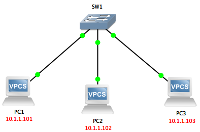
If you have been in the networking industry even for a bit, then you have probably heard of the difference(s) between a hub and a switch. Relevant to our discussion is the fact that when a hub receives a packet, it forwards that packet to all ports on that hub (except the port on which the packet was received), whether that packet is destined to the devices connected to those ports or not.
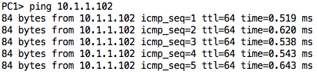
For example, if PC1 wants to send a packet to PC2, the hub will forward that packet out both ports 2 and 3, even though PC3 has no business with that packet.
We can easily see this by looking at a simple lab in GNS3:
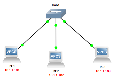
If I ping from PC1 to PC2 while capturing on the link between the hub and PC3, I will see those ping packets also being sent out to PC3 (even though that device will ignore them as they are not addressed to it):

On the other hand, a switch is an intelligent device that is able to forward packets only to the port on which the destination device belongs. To do this, a switch keeps a MAC address table that matches MAC addresses to the ports on which those addresses appear. So when a switch receives a (unicast) packet, it will go through the following steps:
- Check its MAC address table for the MAC address of the destination.
- If the MAC address is found in the table, the switch will forward the packet out only on the interface associated with that MAC address in its table.
- If the MAC address is not in the table, the switch will flood the packet out all interfaces except the interface on which the packet was received. Assuming the packet is part of a ‘string’ of other packets, the switch will eventually learn the port on which the destination device is and start sending packets out only on that interface.
To confirm this behavior of a switch, we can also do the same test we did in the case of the hub; however, we will change the hub to a switch.
We will ping from PC1 to PC2 again while capturing packets off the link between SW1 and PC3:
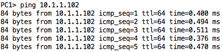

As you can see, the only packet received by PC3 was the ARP request sent by PC1 trying to resolve the IP address of PC2. Once the switch learned the port on which PC2 belongs, it did not forward packets destined to PC2 to its other ports.
Создание RAID-массива или Зеркалирование дисков в новейшей Windows 10 Fall Creators Update
Возьмём обычный компьютер в организации, где я работаю.
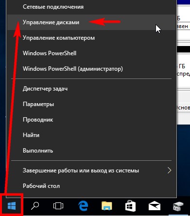
Щёлкаем правой мышью на меню «Пуск» и выберем «Управление дисками».
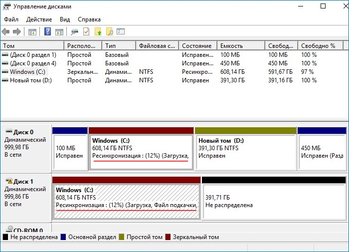
В данном окне вы можете заметить два подключенных к ПК жёстких диска.
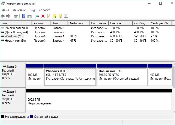
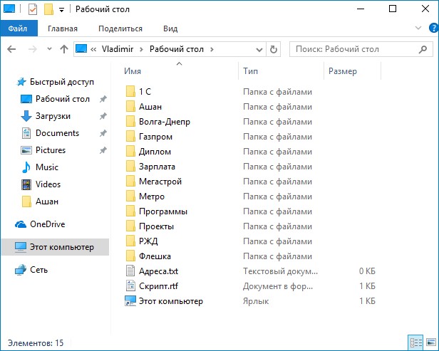
На первом диске (Диск 0) находятся два раздела: (C:) и (D:). На диске (C:) установлена Windows 10. На рабочем столе ОС находятся важные рабочие папки. Если папки по каким-либо причинам пропадут, то работа всей организации остановится на несколько дней и я даже боюсь представить все последствия. На диске (D:) серьёзной информации нет, только киношки и фотографии. Поэтому зеркало я создам для одного системного раздела (C:).
Второй жёсткий диск (Диск 1) абсолютно чистый и не содержит разделов, вся его область нераспределена. Именно на нём мы и создадим зеркало диска (C:). Вся записанная на системный диск информация будет также продублирована на диске — зеркале.
Важно, чтобы HDD, из которого мы хотим создать зеркало, был без разделов и размером не меньше, чем исходный диск, на котором установлена операционная система. В нашем случае оба жёстких диска абсолютно одинаковые.
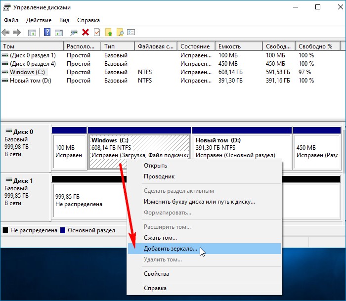
Щёлкаем правой мышью на диске (C:) и выбираем «Добавить зеркало…»
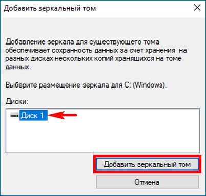
Windows 10 предложит выбрать диск, который мы желаем использовать в качестве зеркала. Выделяем левой кнопкой мыши чистый Диск 1 и жмём «Добавить зеркальный том».
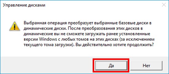
Выходит предупреждение о том, что сейчас диски будут преобразованы в динамические и если на вашем ПК установлено несколько операционных систем, то после преобразования вы сможете загрузить только текущую операционную систему. Объясню.
Настраивать RAID-1 массив или «Зеркалирование дисков» лучше только в том случае, если у вас на компьютере установлена одна операционная система, имеющая один загрузчик. Если на вашем ПК установлено несколько ОС, к примеру, Windows 8.1 и Windows 10, то зеркалить диски можно в той винде, которая была установлена последней. То есть, вы установили Windows 8.1, затем Windows 10, в этом случае настраиваем RAID-1 массив в Windows 10 и после этого на компьютере будет загружаться только Виндовс 10. Если настроить RAID-1 массив в Windows 8.1, то на ПК вообще ни одна винда грузится не будет. Связана эта проблема с особенностью работы динамических дисков, о которой неплохо было бы написать отдельную статью, да всё руки не доходят.
На моём компьютере установлена только одна ОС. Жму «Да».
Начинается процесс ресинхронизации дисков при создании зеркала. Простыми словами, Windows 10 создаёт точную копию диска (C:) на втором жёстком диске (Диск 1). Из нераспределённого пространства вы можете создать раздел и без проблем пользоваться им.
Процесс ресинхронизации закончен и ОС готова к работе.
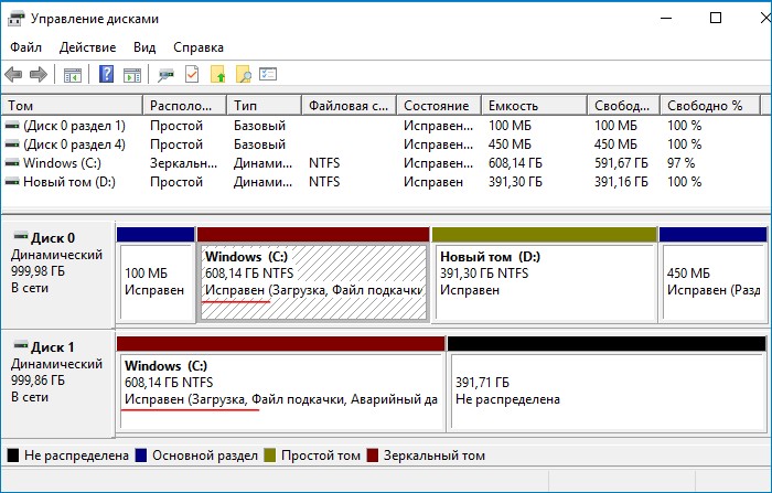
Теперь все изменения на диске (C:) будут зеркально отображаться на его копии, созданной нами на втором жёстком диске. Если вы создадите какой-либо файл на диске (C:), то он тут же создастся на зеркальном диске. Если вы измените тот или иной файл на диске (C:), то он тут же изменится на зеркале. Если HDD с установленной Windows 10 выйдет из строя, то все ваши файлы будут доступны на зеркале.
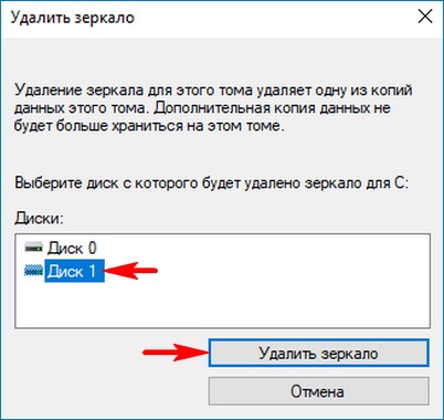
Убрать зеркало также просто, как и создать. Щёлкаем правой мышью на диске (C:) и выбираем «Удалить зеркало…» В нашем случае выбираем Диск 1.
Статьи по этой теме:
- Как создать RAID массив и зачем он нужен
- Как создать RAID 1 массив в случае, если на одном жёстком диске уже имеется информация
Basic RSPAN configuration
RSPAN (Remote SPAN) feature allows traffic that is sourced from a switch to be mirrored to a remote switch within a layer 2 network over trunk ports. To accomplish this you will have to configure the destination VLAN across the entire path between the switches.
In the diagram below, we want to capture traffic from Switch1 (port fa0/1) and send the traffic to Switch2 (port fa0/5).
Although here we show a direct connection with a Layer2 trunk port between Switch1-Switch2, you can have multiple switches between them with no problem (the capturing vlan must be active on the whole path though).

Configuration Commands
Switch1# config term Switch1 (config)# vlan 100 < —This is the capturing VLAN Switch1 (config-vlan)# remote span Switch1(config-vlan)# exit Switch1 (config)# monitor session 10 source interface fa0/1 Switch1 (config)# monitor session 10 destination remote vlan 100Switch2_Remote# config term Switch2_Remote (config)# vlan 100 < —This is the capturing VLAN Switch2_Remote (config-vlan)# remote span Switch2_Remote (config-vlan)# exit Switch2_Remote (config)# monitor session 11 source remote vlan 100 Switch2_Remote (config)# monitor session 11 destination interface fa0/5
All traffic sourced from interface fa0/1 on switch 1 will be forwarded using vlan 100 towards the destination port on remote switch2 where you can sniff the traffic.
Set up SPAN on CatOS switches
More recent Catalyst ranges are shipped with a newer operating system, called CatOS, instead of the older IOS operating system. The commands used to set up SPAN mirroring in these switches is a little different. With this operating system, you create mirroring with just one command instead of two.
The source ports are defined by the first element in this command, which is the “src_mod/src_ports” part. A second port identifier on the command is automatically read as the destination port – that is, the port to which the packet sniffer is attached. The “rx | tx | both” element tells the switch to replicate the packets transmitted from either port, or both.
There is also a set span command to turn off mirroring:
Types of SPAN:
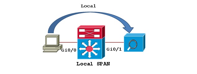
Local SPAN: Mirrors traffic from one or more interface on the switch to one or more interfaces on the same switch.
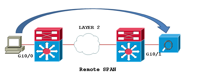
Remote SPAN (RSPAN): An extension of SPAN called remote SPAN or RSPAN. RSPAN allows you to monitor traffic from source ports distributed over multiple switches, which means that you can centralize your network capture devices. RSPAN works by mirroring the traffic from the source ports of an RSPAN session onto a VLAN that is dedicated for the RSPAN session. This VLAN is then trunked to other switches, allowing the RSPAN session traffic to be transported across multiple switches. On the switch that contains the destination port for the session, traffic from the RSPAN session VLAN is simply mirrored out the destination port.
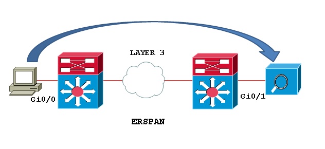
Encapsulated remote SPAN (ERSPAN): encapsulated Remote SPAN (ERSPAN), as the name says, brings generic routing encapsulation (GRE) for all captured traffic and allows it to be extended across Layer 3 domains.
ERSPAN is a Cisco proprietary feature and is available only to Catalyst 6500, 7600, Nexus, and ASR 1000 platforms to date. The ASR 1000 supports ERSPAN source (monitoring) only on Fast Ethernet, Gigabit Ethernet, and port-channel interfaces.
Basic SPAN configuration
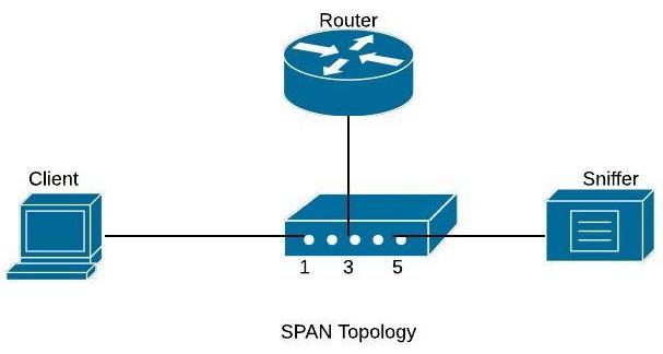
For Network Engineers, the ability to mirror switch traffic and send it to a sniffer for analysis is an essential troubleshooting technique.
All Cisco Catalyst switches support the Switched Port Analyzer (SPAN) feature which copies traffic from specified switch source ports or VLANs and mirrors this traffic to a specified destination switch port (SPAN port).
Then, you can connect your PC having a sniffer tool (like WireShark) on the destination SPAN port to capture all mirrored traffic. The diagram below shows this:
Basic SPAN captures traffic from one source port or VLAN and sends the traffic to another port on the same switch.
On the diagram shown below, we will capture traffic from source port fa0/1 (connected to a user computer) and send the traffic to destination port fa0/5.
Configuration Commands
Switch# configure terminal Switch(config)# monitor session 1 source interface fa0/1 Switch(config)# monitor session 1 destination interface fa0/5
With this simple configuration, traffic sourced from interface fa0/1 will be mirrored to interface fa0/5 where you will be able to capture it.
We can also monitor the traffic of a whole Vlan and send a copy of the traffic to a destination physical port as shown below:
Configuration Example – Monitoring an entire VLAN traffic
c3750(config)#monitor session 1 source vlan 5 c3750(config)#monitor session 1 destination interface fastethernet 0/5
The configuration above will capture all traffic of VLAN 5 and send it to SPAN port fastethernet 0/5.
Use the command show monitor session 1 to verify your configuration.
Зеркальная Windows
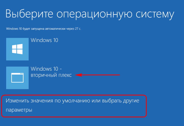
Как только данные будут синхронизированы с зеркалом, а о завершении этого процесса узнаем по степени нагрузки на диск в диспетчере задач, можем перезагружаться и тестировать работоспособность зеркальной Виндовс. Доступ к ней, как упоминалось, появится в меню загрузчика, она будет значится с надписью «Windows такая-то версия – вторичный плекс». Меню загрузчика, кстати, в последних двух версиях ОС можно настроить прямо на этапе запуска компьютера.
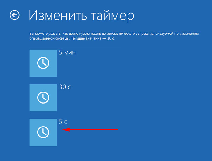
Можно установить меньшее время для автовыбора Windows.
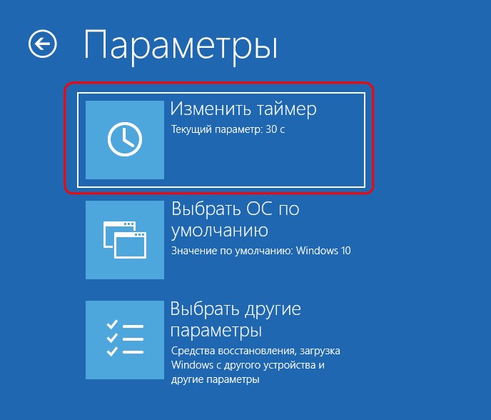
Первой будет загружаться система на основном диске, так что можно выбрать минимальные 5 секунд для отображения вариантов загрузки.
В старых версиях Виндовс таймаут для меню загрузчика настраивается в системной утилите «Конфигурация системы».
Зеркальная Windows — это полный клон основной системы. Здесь можем делать всё то же, что и в оригинальной среде. Если что случается с основным HDD или SSD, отключаем его аппаратно, запускаем компьютер и жмём F9 на экране ошибки загрузки ОС.
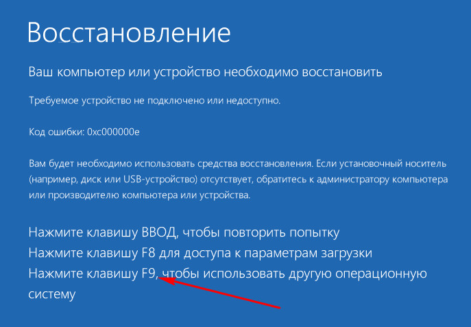
Далее в меню загрузчика выбираем систему с допиской «вторичный плекс», т.е. Windows на зеркальном диске.
Зеркалирование Windows: что это
Зеркалирование — это, как упоминалось, программный RAID 1, часто используемая конфигурация дискового массива, при которой данные дублируются на второй, именуемый зеркалом жёсткий диск. При возникновении неполадок с первым, основным жёстким диском с помощью зеркала сможем получить доступ к нашей ценной информации. Более того, если зеркалирование применятся к системным разделам Windows, при поломке основного диска мы не просто получим доступ к информации, хранящейся в системе, мы даже попадём внутрь неё. Не внутрь неё исходной, но внутрь точного её клона на диске-зеркале.
Реализация программного RAID 1 возможна в условиях работы технологии динамических дисков. Технология эта существует в среде Windows, начиная с версии 2000. Сама технология применима как к MBR-, так и к GPT-дискам, но вот создание программного RAID 1 усложнено необходимостью проведения дополнительных операций с командной строкой. Так что всё, что будет предложено ниже, касается только MBR-дисков. Создание программного RAID возможно только в редакциях ОС, начиная с Pro.
При переустановке системы на динамических дисках не нужно внедрять в дистрибутив специфические драйверы RAID-контроллера, как это требуется при аппаратном RAID. Равно как и не нужно ничего переустанавливать при задействовании любой из конфигураций программного RAID. Однако в условиях работы с динамическими дисками не сможем использовать более одной Windows. Установленные на других разделах ОС просто не загрузятся. Технология работает по правилу «Вход – рубль, выход — два»: в динамический тип исходные базовые диски со структурой и данными средствами Виндовс превращаются легко и просто, а вот обратное направление работает только для дисков с нераспределённой областью. Если структура и данные есть, придётся прибегать к стороннему софту.
Ещё один важный нюанс: для работы с этой технологией важно, чтобы в имени компьютера были только символы латиницей. Иначе получим ошибку «Недопустимое имя пакета».
Paessler Packet Capture Tool

Paessler PRTG is a network monitoring tool that is composed of many individual sensors. One of these tools is a packet capture sensor. This sensor doesn’t come with a physical TAP; instead, it relies on the data supplied in a stream from your switches. This tool offers great data visualizations for both live data and for packets read from file storage.
The great thing about PRTG is that it can offer you different layers of visibility from within the same tool. It also includes sensors that sample network data, capturing just packet headers from different locations on the network. You can also reduce the amount of data that needs to be processed by the monitor by specifying sampling.
As well as the packet sniffing sensor, PRTG includes the following traffic sampling systems:
- A NetFlow sensor
- An sFlow sensor
- A J-Flow sensor
With this system, you could use the NetFlow, sFlow, and J-Flow sensors to get an overview of your entire network and then go to the packet sniffer to focus on the typical flows at one device. Once you have isolated an overloaded switch, you can then home in on the specific ports that have too much traffic and look at the types of traffic that are overwhelming it. With this information, you can either implement traffic shaping measures or choose to add on more infrastructure to reroute heavy traffic points and spread the load.
The packet sniffer sensor only processes the headers of traffic datagrams traveling around the network. This strategy reduces the amount of processing needed to aggregate flow metrics and greatly speeds analysis.
Configuration
I will use the following topology for this example:
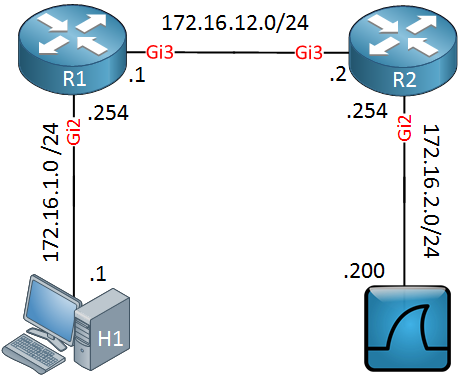
Above we have two routers, R1 and R2. On the left side there’s a host (H1) and on the right side, I have a machine running Wireshark. I will show you how to capture traffic on the Gigabit 2 interface of R2 and send it towards the Wireshark machine behind R2.
Teaser
If you want to try this example, you can use the virtual CSR1000V routers. These run IOS-XE and support ERSPAN.
Let’s start with the configuration on R1:
Above you can see that we capture incoming traffic on the Gigabit 2 interface of R1. We use ERSPAN ID 100, the source IP address will be 172.16.12.1 and the destination is 172.16.2.200 (Wireshark).
Here’s the configuration of R2:
Above we configure the same ERSPAN ID, the destination IP address and the destination interface.
By default, the ERSPAN session will be administratively disabled. You have to use the no shutdown command to enable it.
Encapsulated Remote SPAN (ERSPAN)
Encapsulated Remote SPAN (ERSPAN), as the name says, brings generic routing encapsulation (GRE) for all captured traffic and allows it to be extended across Layer 3 domains.
ERSPAN is a Cisco proprietary feature and is available only to Catalyst 6500, 7600, Nexus, and ASR 1000 platforms to date. The ASR 1000 supports ERSPAN source (monitoring) only on Fast Ethernet, Gigabit Ethernet, and port-channel interfaces.
Related- RSPAN vs ERSPAN
CONFIGURING LOCAL SPAN:
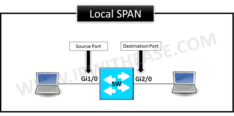
Local SPAN gets configured using the “monitor session” command.
Example:
SW# configure terminalSW(config)# monitor session 1 source interface Gi1/0
SW(config)# monitor session 1 destination interface Gi2/0
SW(config)#end
Local SPAN configuration syntax on Cisco IOS release 12.2(33)SXH and beyond as shown below –
monitor session 1 type localsource int fa0/2
destination int fa0/24
CONFIGURING RSPAN or REMOTE-SPAN :

1st RSPAN step is to configure special VLAN which can’t be assigned to any access port.
Configuring the Special VLAN:
SW1# configure terminalSW1(config)# vlan 200
SW1(config-vlan)# remote-span
SW1(config-vlan)# end
SW1# show vlan remote-span
Remote SPAN VLANs
——————————————————————————
200
SW2# configure terminalSW2(config)# vlan 200
SW2(config-vlan)# remote-span
SW2(config-vlan)# end
SW2# show vlan remote-span
Remote SPAN VLANs
——————————————————————————
200
CONFIGURING RSPAN ON SOURCE SWITCH:
SW1# configure terminalSW1(config)# monitor session 1 source interface gi1/0 rx
SW1(config)# monitor sessioSW1(config)# exit
Here we notice the source switch mirrors the packet from source port towards the reflector port Gi1/1.
n 1 destination remote vlan 200 reflector-port gi1/1
RSPAN Reflector Port
The reflector port forwards only the traffic from the RSPAN source session with which it is affiliated. Any device that is connected to a port that is set as a reflector port loses connectivity until the RSPAN source session is disabled.
If the bandwidth of the reflector port cannot handle the traffic from the corresponding source ports, the excess packets are dropped
The reflector port cannot be an Ether Channel port. In addition, a reflector port does not trunk and cannot do protocol filtering. A port that is used as a reflector port cannot be a SPAN source or destination port, and it cannot be a reflector port for more than one session at a time. Spanning tree is automatically disabled on a reflector port; the port remains in the forwarding state even though the port is in loopback mode.
CONFIGURING Remote SPAN ON DESTINATION SWITCH:
SW2# configure terminalSW2(config)# monitor session 1 source remote vlan 200
SW2(config)# monitor session 1 destination interface gi2/0
SW2(config)# exit
While troubleshooting IPT issues in VOIP domain if a capture isn’t possible to be taken from a IP phone then SPAN is widely used to take the capture from the switch to which the IP phone is connected and all packets from the phones are mirrored to a port where a laptop is connected with a network analyzer to capture real-time traffic.
For more information on the Source port, Destination Port and Remote SPAN VLAN characteristics please refer to link below:
Advertisements
Switches and hubs
A link, or “hop,” on a network is the connection between two devices. The link might be the last stretch that connects an endpoint, or it might be between two network devices. There will always be a network device on at least one end of the link. For traffic within a network, that device will be either a switch or a hub.
A hub transmits all of the traffic that it receives on one of its connections out to all of the others. It doesn’t pay attention to the destination address on the incoming packets. A switch is more selective because it examines packet headers and forwards each to the port that it has listed for that address. The cable connected to that destination port might not lead to the endpoint that is identified by that address. If there is another network device between that switch and the endpoint, the cable that receives the moving data will lead to that intermediate device, which, in turn, will forward it on.
Fortunately, for packet capture, switches and hubs don’t forge temporary physical links between the source and destination ports in a connection. Instead, the device collects the incoming data. It then creates an exact copy of that data and applies it to the destination port. In the case of hubs, this action creates duplication. For example, if a hub receives a packet on one of its ten ports, it will send that same packet out on all of its other nine ports.
So, one packet becomes nine copies. A switch does exactly the same thing with packets that are marked for broadcast. Traffic that is traveling to one destination only gets copied onto the port that the switch has listed for that address. So there continues to be only one instance of that data as it travels out of the switch.
The duplication of packets performed by switches and routers is exactly the same as the work performed by a traffic splitter.
Port mirroring with a hub
As you can see from the descriptions of how switches and hubs work, a hub automatically duplicates all of the traffic that it receives. So, if you only have hubs on your network, it is very easy to get a copy of all of the traffic circulating on it. The hub sends all traffic to all endpoints. If that traffic has to travel through other network devices to reach some of the endpoints on the network, that won’t block the traffic getting to those endpoints if the intermediate devices are also hubs.
As your own computer is connected to one of the hubs on the network, all of the traffic on the network will automatically get sent to your computer without having to alter the settings of the hub. Your computer won’t read in all of that traffic, however.
The firmware on your computer’s network card has an identifier hard-coded into it: this is the MAC address, which stands for “media access controller.” The network card will only react to arriving messages that have that MAC address on them. All others will be ignored. Think of the network card as a doorman at a private club. Anyone arriving has to give a password in order to get in; those without the password get blocked from entering. The MAC address is that password.
If you want to see all of the traffic on a network that is equipped entirely with hubs, all you have to do is tell the network card to drop the requirement for its own MAC address. In network terminology, this setting is called “promiscuous mode.”
Purists will argue that putting your network card in promiscuous mode is not “port mirroring,” because your network card is not duplicating packets. They say the card is just dropping the requirement for its MAC address in order to recognize arriving packets and forward them to applications on your computer.
In truth “port mirroring on a hub” is a redundant concept because the hub duplicates all packets by default. Generally, the term “port mirroring” is only applied to switches.