Dynamic arp protection
Содержание:
- [править] Использование опции 82
- VLANs
- Securing Virtual LAN
- DHCPDISCOVER
- [править] Примеры конфигураций
- [править] Инсталляция и настройка DHCP сервера ISC-DHCP
- Flow Control
- DHCP Client / Static IP
- Site:
- [править]Настройка DHCP snooping на коммутаторах Cisco
- Настройка DHCP для среднего офиса
- MSTP
- [править]Конфигурационные файлы
[править] Использование опции 82
По умолчанию коммутатор на котором включен DHCP snooping, вставляет опцию 82 в DHCP-запросы. Коммутатор может изменять или вставлять опцию 82, даже если клиент и сервер находятся в одной подсети.
При вставке опции 82, коммутатор фактически вставляет два значения:
- Remote ID (MAC-адрес или IP-адрес коммутатора). Это значение можно настраивать;
- Circuit ID (порт с которого пришел запрос). Это значение не настраивается.
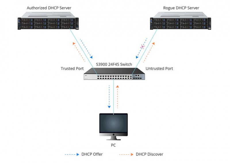
По умолчанию коммутатор, использующий DHCP snooping, обнаруживает и отбрасывает любой DHCP-запрос содержащий опцию 82, который он получил через ненадёжный порт.
Этот режим стоит оставить, если коммутатор соединен с конечными клиентами. Получение запроса с опцией 82 от клиента будет говорит об атаке, которую коммутатор должен предотвратить.
Но если функция DHCP snooping включена на нескольких коммутаторах, которые соединены последовательно, то такое поведение по умолчанию, приведет к тому, что клиенты не смогут получить адрес по DHCP (если сервер находится через несколько коммутаторов).
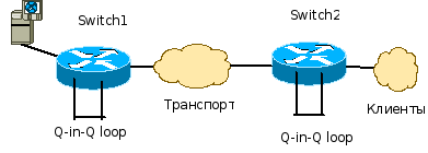
В приведенной схеме такая проблема возникнет:
- Когда sw1 получает запрос от хоста, он проверяет его и, если все в порядке, отправляет дальше. Но при этом, в этот запрос вставляется опция 82
- sw2, при получении запроса на ненадёжном интерфейсе, опять выполняет проверки и, увидев опцию 82 в запросе, отбрасывает его
Есть три способа решения этой проблемы:
Сделать порт a5 на коммутаторе sw2 доверенным
Хотя тогда запросы от хостов и не будут проверяться, чаще всего, это не страшно, так как, все запросы клиентов уже были проверены на sw1
Настроить варианты обработки опции 82 на sw2:
Сохранить опцию 82 в пришедшем пакете
Заменить опцию 82 в пришедшем пакете
Отключить вставку опции 82 на sw1 (может быть не на всем оборудовании)
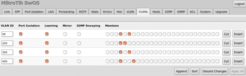
VLANs
|
Description |
USW-Leaf Command |
Cisco Command |
| Display VLAN information, all ports which belong to specific VLAN, and information about the number of VLANs configured on the switch. | UBNT# show bridge-domain | SW# show vlan |
| Create new VLAN 2. | UBNT# configure terminal UBNT(config)# bridge-domain 2 UBNT(bridge-domain)# exit UBNT(config)# |
SW# configure terminal SW(config)# vlan 2 SW(config-vlan)# exit |
|
Add VLAN 2 membership to the port swp1, configure the native VLAN ID 10. NPOS operates VLAN inside bridge-domain, so it’s necessary to associate port with VLAN in bridge-domain. |
UBNT(config)# interface swp1 UBNT(config-if)# switchport mode trunk UBNT(config-if)# switchport trunk allowed vlan 2 UBNT(config-if)# switchport trunk native-vlan 10 UBNT(config-if)# exit UBNT(config)# bridge-domain 2 UBNT(bridge-domain)# vlan 2 swp1 UBNT(bridge-domain)# exit UBNT(config)# bridge-domain 10 UBNT(bridge-domain)# vlan 10 swp1 UBNT(bridge-domain)# exit |
SW(config)# interface fa1/0 SW(config-if)# switchport mode trunk SW(config-if)# switchport trunk allowed vlan add 2 SW(config-if)# switchport trunk native vlan 10 SW(config-if)# exit |
|
Remove VLAN 2 membership from port swp1 and the native VLAN. NPOS port with VLAN association to bridge-domain is removed automatically. |
UBNT(config)# interface swp1 UBNT(config-if)# switchport trunk allowed vlan remove 2 UBNT(config-if)# no switchport trunk native-vlan UBNT(config-if)# exit |
SW(config)# interface fa1/0 SW(config-if)# switchport trunk allowed vlan remove 2 SW(config-if)# no switchport trunk native vlan SW(config-if)# exit |
| Enable or disable dot1q tagging for native VLANs on specific port. Cisco’s method operates dot1q native tagging globally. | UBNT(config)# vlan do1q tag native UBNT(config)# interface swp1 UBNT(config-if)# vlan dot1q tag native UBNT(config-if)# no vlan dot1q tag native UBNT(config-if)# exit | SW(config)# vlan do1q tag native SW(config)# no vlan do1q tag native |
|
Configure the swp1 interface as a nontrunking nontagged single-VLAN 3 access mode. Before switching, disable the current mode. |
UBNT(config)# interface swp1 UBNT(config-if)# no switchport UBNT(config-if)# switchport mode access UBNT(config-if)# switchport access vlan 3 UBNT(config-if)# exit UBNT(config)# bridge-domain 3 UBNT(bridge-domain)# vlan 3 swp1 UBNT(bridge-domain)# exit |
SW(config)# interface fa1/0 SW(config-if)# switchport mode access SW(config-if)# switchport access vlan 3 SW(config-if)# exit |
| Remove any configuration specific to Layer 2 on this interface (include VLAN’s membership), switch interface to Layer 3 mode. | UBNT(config)# interface swp1 UBNT(config-if)# no switchport UBNT(config-if)# exit |
SW(config)# interface fa1/0 SW(config-if)# no switchport SW(config-if)# exit |
|
Disable MAC address learning on a specified VLAN 2. Maximum number of learning MAC records equal 1000. Configure a secure sticky MAC address for interface swp1. |
UBNT(config)# bridge-domain 2 UBNT(bridge-domain)# no learning enable UBNT(bridge-domain)# learning limit 1000 UBNT(bridge-domain)# learning sticky aa:bb:cc:dd:11:22 interface swp1 UBNT(bridge-domain)# exit |
SW(config)# no mac-address-table learning vlan 2 SW(config)# mac-address-table limit vlan 2 maximum 1000 SW(config)# interface fa1/0 SW(config-if)# switchport port-security mac-address aa:bb:cc:dd:11:22 SW(config-if)# exit |
Securing Virtual LAN
In local networks, Virtual Local Area Networks (VLANs) are sometimes configured as a security measure to limit the number of hosts susceptible to layer 2 attacks. VLANs create network boundaries, over which broadcast (ARP, DHCP) traffic cannot cross.
Virtual Local Area Network
A network employing switch/es supporting VLAN capabilities can be configured to define multiple VLANs over a single physical LAN infrastructure.
The common form of VLAN is a port-based VLAN. In this VLAN structure, the switch ports are grouped into VLAN using switch management software. Thus a single physical switch can act as multiple virtual switches.
Employment of VLANs provide traffic isolation. It divides the large broadcast layer 2 network into smaller logical layer 2 networks and thus reduces the scope of attacks such as ARP/DHCP Spoofing. Data frames of one VLAN can move from/to within ports belonging to the same VLAN only. The frames forwarding between two VLANs is done through routing.
VLANs generally span multiple switches as shown in the diagram above. The link between trunk ports carry frames of all VLANs defined over multiple physical switches. Hence, VLAN frames forwarded between switches can’t be simple IEEE 802.1 Ethernet format frames. Since, these frame move on same physical link, they now need to carry VLAN ID information. IEEE 802.1Q protocol adds/removes additional header fields to plain Ethernet frames forwarded between trunk ports.
When the field following the two IP addresses fields is 0x8100 (> 1500), the frame is identified as 802.1Q frame. Value of 2-byte Tag Protocol Identifier (TPI) is 81-00. TCI field consist of 3-bit priority information, 1-bit Drop eligible indicator (DEI), and 12-bit VLAN ID. This 3-bit priority field and DEI field are not relevant to VLANs. Priority bits are used for provision of Quality of Service.
When a frame does not belong to any VLAN, there is a default VLAN id which the frame is considered to be associated with.
Attack on VLAN & Prevention Measures
In a VLAN hopping attack, an attacker on one VLAN can gain access to the traffic on other VLANs that would normally not be accessible. It would bypass a layer 3 device (router) when communicating from one VLAN to another, thus defeating the purpose of VLAN creation.
VLAN hopping can be performed by two methods; switch spoofing and double tagging.
Switch Spoofing
It can occur when the switch port, to which the attacker is connected, is either in ‘trunking’ mode or ‘auto-negotiation’ mode. The attacker acts as a switch and adds 802.1Q encapsulation headers with VLAN tags for target remote VLANs to its outgoing frames. The receiving switch interprets those frames as sourced from another 802.1Q switch, and forwards the frames into the target VLAN.
The two preventive measures against switch spoofing attacks are to set edge ports to static access mode and to disable auto-negotiation on all ports.
Double Tagging
In this attack, an attacker connected on native VLAN port of switch prepends two VLAN tags in the frame header. The first tag is of native VLAN and second is for target VLAN. When the first switch receives the attacker’s frames, it removes the first tag since frames of native VLAN are forwarded without tag on trunk port.
-
Since the second tag was never removed by the first switch, the receiving switch identifies the remaining tag as the VLAN destination and forwards the frames to the target host in that VLAN. The double tagging attack exploits the concept of native VLAN. Since VLAN 1 is the default VLAN for access ports and the default native VLAN on trunks, it’s an easy target.
-
The first prevention measure is to remove all access ports from the default VLAN 1 since the attacker’s port must match that of the switch’s native VLAN. The second prevention measure is to assign the native VLAN on all switch trunks to some unused VLAN, say VLAN id 999. And lastly, all switches be configured to carry out explicit tagging of native VLAN frames on the trunk port.
DHCPDISCOVER
И так, последний этап атаки. После отправки DHCPDECLINE клиент с самого начала проходит процедуру получения IP-адреса, а именно отправляет широковещательный DHCPDISCOVER. Легитимный DHCP-сервер не может ответить на этот запрос, так как пул свободных IP-адресов переполнен после проведения атаки DHCP starvation и поэтому заметно тормозит, зато на DHCPDISCOVER можем ответить мы — 192.168.1.172.
Клиент 84:16:F9:19:AD:14 (Win10-desktop) отправляет широковещательный DHCPDISCOVER:
Отвечаем DHCPOFFER:
В DHCPOFFER мы предложили клиенту IP-адрес 192.168.1.2. Клиент получив данное предложение только от нас отправляет DHCPREQUEST, выставляя при этом в requested ip значение 192.168.1.2.
Клиент 84:16:F9:19:AD:14 (Win10-desktop) отправляет широковещательный DHCPREQUEST:
Отвечаем DHCPACK:
Клиент принимает наш DHCPACK и в качестве шлюза по умолчанию и DNS-сервера выставляет наш IP-адрес: 192.168.1.172, а DHCPNAK от точки доступа присланный на 2 секунды позже просто проигнорирует.
Вопрос: Почему точка доступа прислала DHCPOFFER и DHCPNAK на 2-е секунды позже, да еще и предложила тот же IP-адрес 192.168.1.102, ведь клиент отказался от него?
Чтобы ответить на данный вопрос немного изменим фильтр в WireShark и посмотрим ARP запросы от точки доступа:
Ответ: После проведения атаки DHCP Starvation у DHCP-сервера не оказалось свободных IP-адресов, кроме того, от которого отказался один из клиентов: 192.168.1.102. Поэтому, получив DHCPDISCOVER-запрос, DHCP-сервер в течении 2-ух секунд отправляет три ARP-запроса, чтобы узнать кто использует IP-адрес: 192.168.1.102, и после того, как сервер убедился что данный IP-адрес свободен, поскольку никто не ответил, выдает его клиенту. Но уже слишком поздно злоумышленник успел ответить быстрее.
[править] Примеры конфигураций
Пример конфигурации маршрутизатора Cisco
!
version 12.4
!
hostname Router
!
!
ip dhcp excluded-address 192.168.20.1
ip dhcp excluded-address 192.168.30.1
ip dhcp excluded-address 192.168.40.1
ip dhcp excluded-address 192.168.50.1
ip dhcp excluded-address 192.168.90.1
!
ip dhcp pool guest
   network 192.168.20.0 255.255.255.0
   default-router 192.168.20.1
!
ip dhcp pool marketing
   network 192.168.30.0 255.255.255.0
   default-router 192.168.30.1
!
ip dhcp pool sales
   network 192.168.40.0 255.255.255.0
   default-router 192.168.40.1
!
ip dhcp pool restricted
   network 192.168.50.0 255.255.255.0
   default-router 192.168.50.1
!
ip dhcp pool unauthenticated
   network 192.168.90.0 255.255.255.0
   default-router 192.168.90.1
!
!
!
interface FastEthernet0/0
 ip address 192.168.1.1 255.255.255.0
!
interface FastEthernet0/0.20
 encapsulation dot1Q 20
 ip address 192.168.20.1 255.255.255.0
!
interface FastEthernet0/0.30
 encapsulation dot1Q 30
 ip address 192.168.30.1 255.255.255.0
!
interface FastEthernet0/0.40
 encapsulation dot1Q 40
 ip address 192.168.40.1 255.255.255.0
!
interface FastEthernet0/0.50
 encapsulation dot1Q 50
 ip address 192.168.50.1 255.255.255.0
!
interface FastEthernet0/0.90
 encapsulation dot1Q 90
 ip address 192.168.90.1 255.255.255.0
!
[править] Инсталляция и настройка DHCP сервера ISC-DHCP
Будем использовать dhcp-сервер ISC-DHCP (v3)
ISC DHCP Server — наиболее распространнённый DHCP-сервер, из использующихся в UNIX/Linux-системах.
Для нас сейчас важно и то, что это один из серверов, умеющих распознавать опцию 82
Будем предполагать, что инсталляция и настройка сервера
выполняется в Debian GNU/Linux. Пользователи других систем
должны учесть, что процедура инсталляции
и местоположение конфигурационных файлов могут несколько отличаться.
Установка DHCP-сервера с поддержкой опции 82
В обычном случае установить откомпилированный DHCP-сервер из репозитория пакетов
можно было бы с помощью команды:
%# apt-get install dhcp3-server
и можно было бы считать, что на этом инсталляция сервера закончена,
и можно переходить к его настройке. Однако, в том случае, если предполагается использование
DHCP-ретранслятора (что обязательно, если будет использоваться опция 82),
может потребоваться сборка пакета с включённой директивой USE_SOCKETS.
Подробнее эта процедура описана ниже.
Сборка с включённой директивой USE_SOCKETS
По умолчанию DHCP-сервер ожидает услышать запросы клиентов на широковещательном адрес 255.255.255.255. Однако, когда запрос перенаправляет DHCP-ретранслятор, запрос приходит непосредственно на адрес DHCP-сервера.
Для того чтобы DHCP-сервер корректно обрабатывал информацию от DHCP-ретранслятора,
его необходимо скомпилировать с использованием директивы
#define USE_SOCKETS
и указать в конфигурационном файле local-address.
Скачиваем исходники DHCP-сервера:
%# apt-get source dhcp3-server
Перед началом сборки исходников необходимо установить все пакеты,
необходимые для успешной сборки пакета, для чего выполнить:
%# apt-get build-dep dhcp3-server
Теперь необходимо в файле site.h раскомментировать директиву #define USE_SOCKETS:
%# vi dhcp3-3.0.6.dfsg/includes/site.h
Перейти в каталог dhcp3-3.0.6.dfsg:
%# cd dhcp3-3.0.6.dfsg/
Для того чтобы собрать пакет необходимо выполнить:
%$ dpkg-buildpackage -rfakeroot -b
или, если сборка производится root’ом:
%# dpkg-buildpackage -b
После сборки пакеты должны быть установлены в системе
(инсталлируем только common и server, так как нам не нужен DHCP-ретранслятор и DHCP-клиент):
%# dpkg -i dhcp3-common_3.0.6.dfsg-1_i386.deb dhcp3-server_3.0.6.dfsg-1_i386.deb
Настройка DHCP-сервера
Сразу же после инсталляции пакета,
сервер не заработает — сначала необходимо
отредактировать его конфигурационный файл /etc/dhcp3/dhcpd.conf.
# Укажите адрес, на который DHCP-сервер ожидает получать запросы (адрес DHCP-сервера)

local-address 192.168.2.9;

# Укажите подсеть интерфейса, на котором запущен DHCP-сервер

subnet 192.168.2.0 netmask 255.255.255.0 {
}

# Если сервер получит запрос, содержащий опцию 82, он сгенерирует сообщение в системный журнал
#

if exists agent.circuit-id
{
 log ( info, concat( " Lease for ",
                     binary-to-ascii (10, 8, ".", leased-address),
                     " Switch port: ",
                     binary-to-ascii (10, 8, ".", option agent.circuit-id),
                     " Switch MAC: ",
                     binary-to-ascii(16, 8, ".", option agent.remote-id)));
}

# Запросы, пришедшие с 5го порта коммутатора:
class "port-5"
{
 match if binary-to-ascii (10, 8, "", suffix( option agent.circuit-id, 1)) = "5";
}

# Адрес для 5го порта:
pool {
  range 192.168.1.55;
  allow members of "port-5";
}
Интерфейс, на котором будет работать DHCP-сервер,
передается ему в качестве аргумента при вызове.
В Debian GNU/Linux аргументы и ключи вызова программ
принято указывать в соответствующих файлах в каталоге /etc/default,
в частности, конфигурационный файл, в котором находятся опции для нашего сервера,
называется /etc/default/dhcp3-server.
При условии, что сервер будет слушать запросы на интерфейсе eth0,
файл будет выглядеть так:
# On what interfaces should the DHCP server (dhcpd) serve DHCP requests?
# Separate multiple interfaces with spaces, e.g. "eth0 eth1".
INTERFACES="eth0"
Можно указать несколько интерфейсов,
запросы с которых будет обрабатывать сервер.
Они должны быть разделены пробелом.
Теперь можно запускать сервер:
%# /etc/init.d/dhcp3-server start
После сборки сервера с #define USE_SOCKETS:
udp     0   0 192.168.2.9:67    0.0.0.0:*   863/dhcpd3
udp     0   0 192.168.2.9:67    0.0.0.0:*   863/dhcpd3
Flow Control
|
Description |
USW-Leaf Command |
Cisco Command |
|
*Display the flow control settings. |
N/A |
SW# show interface flowcontrol |
|
Configure flow-control mode Configure flow-control priority |
UBNT(config)# interface swp1 UBNT(config-if)# flow-control mode both UBNT(config-if)# priority-flow-control mode both UBNT(config-if)# exit |
SW(config)# interface ethernet fa0/1 SW(config-if)# flowcontrol receive on SW(config-if)# flowcontrol send on SW(config-if)#priority-flow-control mode on SW(config-if)# exit |
| Disable Link Level Flow Control and its priority on a specific interface. | UBNT(config)# interface swp1 UBNT(config-if)# no flow-control UBNT(config-if)# no priority-flow-control UBNT(config-if)# exit |
SW(config)# interface ethernet fa0/1 SW(config-if)# flowcontrol receive off SW(config-if)# flowcontrol send off SW(config-if)#priority-flow-control mode off SW(config-if)# exit |
DHCP Client / Static IP
|
Description |
USW-Leaf Command |
Cisco Command |
| Overview all IPv4 interfaces on the switch. | UBNT# show ip interface brief | SW# show ip interface brief |
| Enable/Disable DHCP Client on bridge-domain interface. | UBNT(config)# interface bridge 1 UBNT(config-if)# ip address dhcp UBNT(config-if)# no ip address dhcp UBNT(config-if)# exit | SW(config)# interface vlan1 SW(config-if)# ip address dhcp SW(config-if)# no ip address dhcp SW(config-if)# exit |
| Configure/Remove static IP address on interface. | UBNT(config)# interface swp1 UBNT(config-if)# ip address 172.16.0.1/24 UBNT(config-if)# no ip address 172.16.0.1/24 UBNT(config-if)# exit | SW(config)# interface gigabitEthernet 1/0/1 SW(config-if)# ip address 172.16.0.1 255.255.255.0 SW(config-if)# no ip address 172.16.0.1 SW(config-if)# exit |
Site:
Site Configuration:
Site Name:
Here you can tell the controller what name your site should be displayed as. Standard it’s marked as default, but especially when having multiple physical networks in a single controller, it can be useful to change this.
Country:
The country that the site resides in, defines a few things:
- Each country has its own regulations regarding maximum output power and available channels. The US for instance, allows a maximum total power output of 36 dbi, while the Netherlands only allows 20 dbi. This is similar as with channels on both the 2.4 and 5 ghz radio’s.
- It also is for assigning the location in your controller, so that you can distinguish between instances.
You might be thinking «well, i’ll just change my settings to another country, so that I can crank up my power on my access points.» But because each country comes with it’s own channels, this usually doesn’t work. Also keep in mind, when designing a network for use in situations where you might expect frequent visitors from other countries, that their equipment might not support all channels that are common in your country.
Time Zone
Here you can select the time zone your network is in. This impacts the scheduling feature for updating firmware.
Services:
Advanced Features:
Enabling this feature will unlock the following settings:
- Airtime fairness
- Band steering
- Minimum RSSI
- Load Balancing
[править]Настройка DHCP snooping на коммутаторах Cisco
Включить DHCP snooping:
sw2(config)# ip dhcp snooping
Включить DHCP snooping в VLAN, которые должны быть защищены с его помощью:
sw2(config)# ip dhcp snooping vlan 10
| После включения DHCP snooping в VLAN, коммутатор перестает отправлять DHCP-сообщения от клиента на все порты VLAN. Сообщения по-прежнему отправляются на широковещательный адрес, но теперь коммутатор будет передавать их только на доверенные порты, так как только на них может находиться DHCP-сервер. |
Настройка доверенных и ненадёжных портов
По умолчанию на коммутаторе все порты ненадёжные, поэтому доверенные порты надо явным образом указывать.
Указать доверенные порты:
sw2(config)# interface fa 0/1
sw2(config-if)# ip dhcp snooping trust
(Опционально) Указать адрес авторизованного DHCP-сервера, доступного через доверенный порт:
sw2(config)#ip dhcp-server 10.84.168.253
По умолчанию, после включения DHCP snooping, на коммутаторе включена проверка соответствия MAC-адресов. Коммутатор проверяет соответствие MAC-адреса в DHCP-запросе MAC-адресу клиента. Если они не соответствуют, то коммутатор отбрасывает пакет.
При необходимости можно отключить эту проверку:
switch(config)# no ip dhcp snooping verify mac-address
Добавление статических записей в базу данных привязки DHCP
Добавление статической записи в базу данных привязки DHCP:
sw2#ip dhcp snooping binding <mac-address> vlan <vid> <ip-address> interface <interface-id> expiry <seconds>
Настройка опции 82
С опцией 82 связаны две настройки:
- Настройка значения remote ID;
- Настройка политики обработки пакетов с опцией 82.
Настройка remote ID (по умолчанию используется MAC-адрес коммутатора):
sw2(config)# ip dhcp snooping information option format remote-id
Настройка политики обработки пакетов с опцией 82. Коммутатор не будет отбрасывать пакеты, в которых есть опция 82:
sw2(config)# ip dhcp snooping information option allow-untrusted
Отключить вставку опции 82:
switch(config)# no ip dhcp snooping information option
Просмотр настроек и проверка работы DHCP snooping
Просмотр настроек DHCP snooping:
sw2# show ip dhcp snooping
Просмотр статистики DHCP snooping:
sw2# show ip dhcp snooping statistics
Просмотр базы данных привязки DHCP:
sw2# show ip dhcp snooping binding
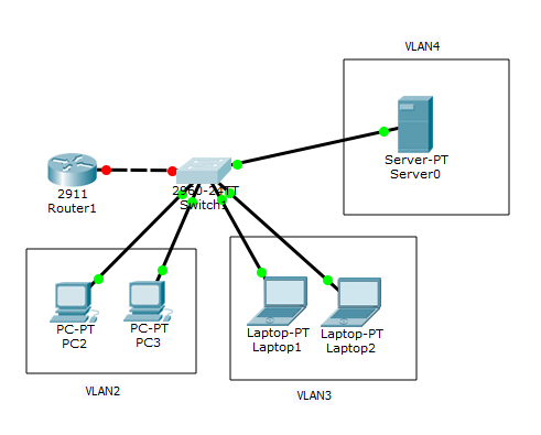
Настройка DHCP для среднего офиса
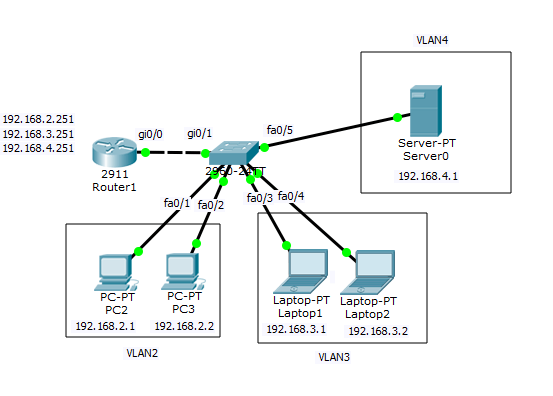
С маленьким офисом мы разобрались, теперь рассмотрим схему среднего офиса. У нас тут уже есть сигментирование в виде vlan (2,3,4). У нас в схеме есть роутер Cisco 2911, на котором будет маршрутизация локального трафика между vlan, коммутатор второго уровня Cisco 2960 на уровне доступа конечных устройств, сервер DHCP в vlan 4, с которого мы и будем получать ip адреса.
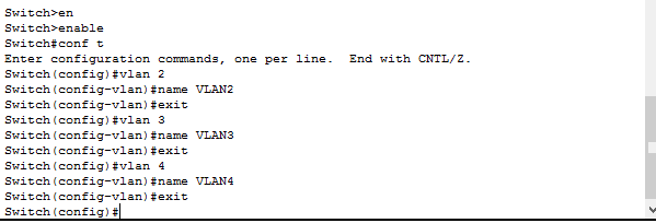
Настроим Cisco 2960
Первым делом на коммутаторе нужно создать vlan 2,3,4 и зададим им имена.
Теперь настроим порты коммутатора и добавим их в нужный vlan.
int range fa0/1-2 switchport mode access switchport access vlan 2 exit
VLAN3 у меня порты fa0/3 и fa0/4
int range fa0/3-4 witchport mode access switchport access vlan 3 exit
VLAN4 у меня порт fa0/5
int fa 0/5 switchport mode access switchport access vlan 4 exit
Теперь настроим порт gi0/1 который подключается к роутеру Cisco 2911, и режим работы у него будет trunk. разрешим через trunk все 4 vlan.
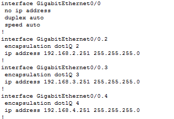
Настроим Cisco 2911
Теперь приступим к настройке Cisco 2911, на нем будет маршрутизация трафика между vlan, значит для этого мы должны создать их на нем, задать им ip адреса, которые будут выступать в роли шлюзов.Вот общая схема.
первым делом мы поднимаем порт, так как на всех роутерах Cisco они в выключенном состоянии.

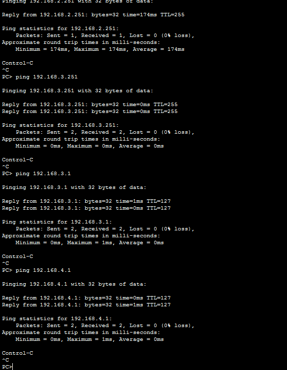
Проверим теперь с компьютера где ip адрес 192.168.2.1 пропинговать шлюз и соседей по vlan 3,4. Видим, что все отлично работает, связь проверена. Осталось теперь настроить DHCP сервер.
DHCP настройка
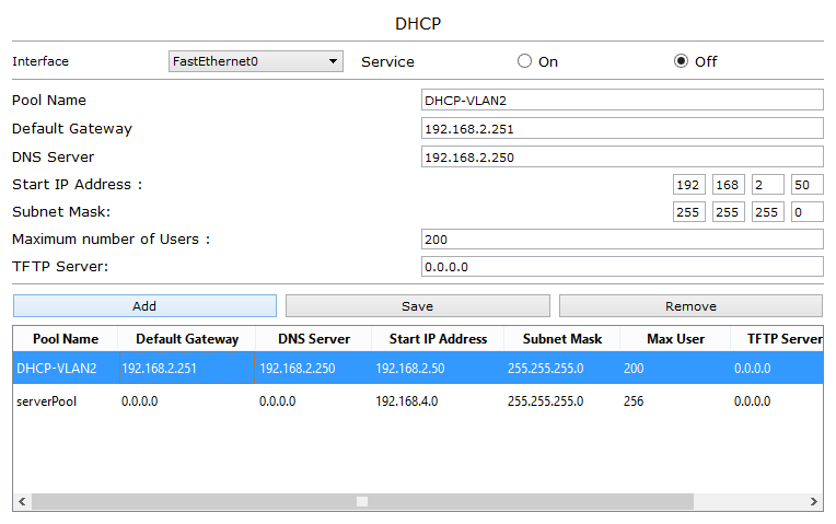
Напомню, что службой DHCP, может быть компьютер с роль на Windows Server (тут это компьютер или виртуальная машина, где есть много сетевых интерфейсов, каждый из которых подключен к нужному vlan, в который DHCP и отдает свои ip адреса), само устройство cisco, либо сторонний продукт на базе linux, вариантов много, в своей тестовой среде у меня это будет сервер в cisco packet tracer, у него есть статический ip адрес 192.168.4.1. Я создаю новый пул для VLAN2, раздавать я буду с 192.168.2.50 до 192.168.2.250, задаю шлюз по умолчанию и dns сервер.
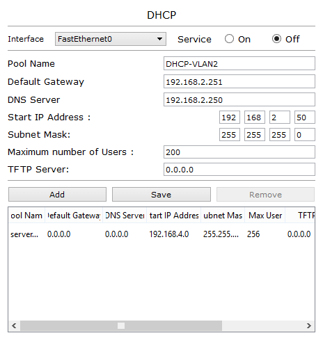
жмем Add и добавляем наш пул. Так же создаем пул для 3 VLAN.
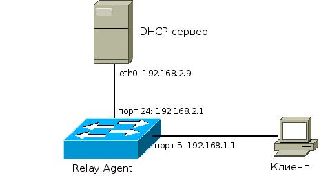
Теперь вспомним, что у нас DHCP сервер в другом vlan, а это значит что широковещательные запросы DHCPDISCOVER из других vlan он не видит, решить эту проблему нам поможет dhcp relay.
MSTP
|
Description |
USW-Leaf Command |
Cisco Command |
| Display Multiple Spanning Tree configuration information. | UBNT# show spanning-tree mst configuration | SW# show spanning-tree mst configuration |
| Display Multiple Spanning Tree specific instance information. | UBNT# show spanning-tree mst 1 status | SW# show spanning-tree mst 1 |
| Displays a brief summary about specific MSTP instance. | UBNT# show spanning-tree mst 1 interface brief | |
| Configure Multiple Spanning Tree Properties. | UBNT(config)# spanning-tree mode mst UBNT(config)# spanning-tree mst max-hops 22 UBNT(config)# spanning-tree mst name test_inst UBNT(config)# spanning-tree mst revision 32768 | SW(config)# spanning-tree mode mst SW(config)# spanning-tree mst max-hops 22 SW(config)# spanning-tree mst configuration SW(config-mst)# name test_inst SW(config-mst)# revision 32768 SW(config-mst)# exit |
| Configure instance priority, and add VLAN 100 to MST instance 2. | UBNT(config)# spanning-tree mst 2 priority 61440 UBNT(config)# spanning-tree instance 2 domain 100 | SW(config)# spanning-tree mst 2 priority 61440 SW(config)# spanning-tree mst configuration SW(config-mst)# instance 2 vlan 100 SW(config-mst)# exit |
| *STP/MSTP interface related commands for special interface(swp1) in specific vlan(100). | UBNT(config-if)# interface swp1.100 UBNT(config-if)# spanning-tree link-type point-to-point UBNT(config-if)# spanning-tree cost 10000 UBNT(config-if)# spanning-tree port-priority 32 UBNT(config-if)# spanning-tree edge-port | SW(config)# interface gigabitEthernet 1/0/1 SW(config-if)# spanning-tree link-type point-to-point SW(config-if)# spanning-tree mst <instance-id> port-priority 32 SW(config-if)# spanning-tree mst <instance-id> cost 10000 SW(config-if)# spanning-tree portfast |
[править]Конфигурационные файлы
DHCP-сервер
Конфигурационный файл DHCP-сервера:
ddns-update-style none;
default-lease-time 600;
max-lease-time 7200;
log-facility local7;

subnet 192.168.25.0 netmask 255.255.255.0 {
  range 192.168.25.200 192.168.25.220;
  option routers 192.168.25.254;
}

subnet 192.168.10.0 netmask 255.255.255.0 {
  range 192.168.10.10 192.168.10.15;
  option routers 192.168.10.1;
}

subnet 192.168.30.0 netmask 255.255.255.0 {
  range 192.168.30.10 192.168.30.15;
  option routers 192.168.30.1;
}
Коммутаторы ProCurve
Конфигурация sw1:
; J4906A Configuration Editor; Created on release #M.10.41

hostname "sw1"
vlan 1
   name "DEFAULT_VLAN"
   untagged 2-6,8-48
   ip address dhcp-bootp
   no untagged 1,7
   exit
vlan 10
   name "VLAN10"
   untagged 1
   tagged 24
   exit
vlan 30
   name "VLAN30"
   untagged 7
   tagged 24
   exit

# Включение DHCP snooping
dhcp-snooping

# Включение DHCP snooping в VLAN'ах 1, 10, 30
dhcp-snooping vlan 1 10 30

# Настройка 24 порта доверенным
interface 24
   dhcp-snooping trust
   exit
Конфигурация sw2:
; J8697A Configuration Editor; Created on release #K.13.23

hostname "sw2"
module 1 type J8705A
interface A10
   disable
exit
ip routing
snmp-server community "public" Unrestricted
vlan 1
   name "DEFAULT_VLAN"
   untagged A2-A24
   ip address dhcp-bootp
   no untagged A1
   exit
vlan 10
   name "VLAN10"

# По умолчанию на коммутаторе включен DHCP-ретранслятор.
# ip helper-address указывает куда перенаправлять DHCP-запросы.
# 192.168.25.254 — адрес DHCP-сервера.
# Теперь все DHCP-запросы полученные в этом VLAN будут перенаправлены на адрес 192.168.25.254.
   ip helper-address 192.168.25.254
   ip address 192.168.10.1 255.255.255.0
   tagged A5
   exit
vlan 30
   name "VLAN30"

# ip helper-address указывает куда перенаправлять DHCP-запросы.
   ip helper-address 192.168.25.254
   ip address 192.168.30.1 255.255.255.0
   tagged A5
   exit
vlan 25
   name "VLAN25"
   untagged A1
   ip address 192.168.25.1 255.255.255.0
   exit

# Включение DHCP snooping
dhcp-snooping

# Задание адреса авторизованного DHCP-сервера
dhcp-snooping authorized-server 192.168.25.254

# Настройка политики обработки опции 82.
# Так как на коммутаторе sw1 включен DHCP snooping,
# то на коммутатор sw2 DHCP-запросы приходят с опцией 82.
# По умолчанию коммутатор такие пакеты отбрасывает.
# Эта политика указывает, что опцию 82 в пришедших пакетах надо заменить.
dhcp-snooping option 82 untrusted-policy replace

# Включение DHCP snooping в VLAN'ах 1, 10, 25, 30
dhcp-snooping vlan 1 10 25 30

# Настройка порта a1 доверенным
interface A1
   dhcp-snooping trust
   exit