Esp32 и файловая система spiffs
Содержание:
Compression with Shox96
(Shox96 is deprecated and Unishox explained below will be supported in future).
This implementation of includes two functions and for compressing and decompressing text data.
Shox96 is a compression technique developed for reducing storage size of Short Strings. Details of how it works can be found here.
As of now it can work on only strings made of ‘A to Z’, ‘a to z’, ‘0-9’, Special Characters such as &*() etc. found on keyboard, CR, LF, TAB and Space.
In general it can achieve upto 40% size reduction for Short Strings.
Usage
The following set of commands demonstrate how compression can be accomplished:
create table test (b1 blob);
insert into test values (shox96_0_2c('Hello World'));
insert into test values (shox96_0_2c('Lorem Ipsum is simply dummy text of the printing and typesetting industry. Lorem Ipsum has been the industry''s standard dummy text ever since the 1500s, when an unknown printer took a galley of type and scrambled it to make a type specimen book.'));
select txt, length(txt) txt_len from (select shox96_0_2d(b1) txt from test);
select length(b1) compressed_len from test;
See screenshots section for output.
Limitations (for Shox96)
- Trying to decompress any blob that was not compressed using will crash the program.
- It does not work if the string has binary characters. that is, other than ASCII 32 to 126, CR, LF and Tab.
- Dictionary based compression / decompression is not yet implemented.
ESP32 BLE Server
To create an ESP32 BLE Server, open your Arduino IDE and go to File > Examples > ESP32 BLE Arduino and select the BLE_server example. The following code should load:
For creating a BLE server, the code should follow the next steps:
- Create a BLE Server. In this case, the ESP32 acts as a BLE server.
- Create a BLE Service.
- Create a BLE Characteristic on the Service.
- Create a BLE Descriptor on the Characteristic.
- Start the Service.
- Start advertising, so it can be found by other devices.
How the code works
Let’s take a quick look at how the BLE server example code works.
It starts by importing the necessary libraries for the BLE capabilities.
Then, you need to define a UUID for the Service and Characteristic.
You can leave the default UUIDs, or you can go to uuidgenerator.net to create random UUIDs for your services and characteristics.
In the setup(), it starts the serial communication at a baud rate of 115200.
Then, you create a BLE device called “MyESP32”. You can change this name to whatever you like.
In the following line, you set the BLE device as a server.
After that, you create a service for the BLE server with the UUID defined earlier.
Then, you set the characteristic for that service. As you can see, you also use the UUID defined earlier, and you need to pass as arguments the characteristic’s properties. In this case, it’s: READ and WRITE.
After creating the characteristic, you can set its value with the setValue() method.
In this case we’re setting the value to the text “Hello World says Neil”. You can change this text to whatever your like. In future projects, this text can be a sensor reading, or the state of a lamp, for example.
Finally, you can start the service, and the advertising, so other BLE devices can scan and find this BLE device.
This is just a simple example on how to create a BLE server. In this code nothing is done in the loop(), but you can add what happens when a new client connects (check the BLE_notify example for some guidance).
GATT
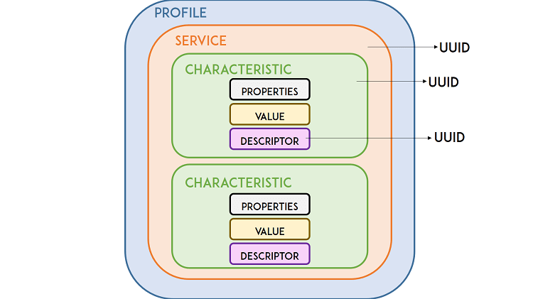
GATT stands for Generic Attributes and it defines an hierarchical data structure that is exposed to connected BLE devices. This means that GATT defines the way that two BLE devices send and receive standard messages. Understanding this hierarchy is important, because it will make it easier to understand how to use the BLE and write your applications.
BLE Service
The top level of the hierarchy is a profile, which is composed of one or more services. Usually, a BLE device contains more than one service.
Every service contains at least one characteristic, or can also reference other services. A service is simply a collection of information, like sensor readings, for example.
There are predefined services for several types of data defined by the SIG (Bluetooth Special Interest Group) like: Battery Level, Blood Pressure, Heart Rate, Weight Scale, etc. You can check here other defined services.

BLE Characteristic
The characteristic is always owned by a service, and it is where the actual data is contained in the hierarchy (value). The characteristic always has two attributes: characteristic declaration (that provides metadata about the data) and the characteristic value.
Additionally, the characteristic value can be followed by descriptors, which further expand on the metadata contained in the characteristic declaration.
The properties describe how the characteristic value can be interacted with. Basically, it contains the operations and procedures that can be used with the characteristic:
- Broadcast
- Read
- Write without response
- Write
- Notify
- Indicate
- Authenticated Signed Writes
- Extended Properties
UUID
Each service, characteristic and descriptor have an UUID (Universally Unique Identifier). An UUID is a unique 128-bit (16 bytes) number. For example:
There are shortened UUIDs for all types, services, and profiles specified in the SIG (Bluetooth Special Interest Group).
But if your application needs its own UUID, you can generate it using this UUID generator website.
In summary, the UUID is used for uniquely identifying information. For example, it can identify a particular service provided by a Bluetooth device.
The final code
You can check the full source code bellow, for an easy copy and paste. Don’t forget to change the values of the global variables by the credentials of your WiFi network. Also note that as said in a previous section, we are not going to use the main loop function, so we can leave it empty.
#include <WiFi.h>

const char* ssid = "yourNetworkName";
const char* password =  "yourNetworkPassword";

String translateEncryptionType(wifi_auth_mode_t encryptionType) {

  switch (encryptionType) {
    case (WIFI_AUTH_OPEN):
      return "Open";
    case (WIFI_AUTH_WEP):
      return "WEP";
    case (WIFI_AUTH_WPA_PSK):
      return "WPA_PSK";
    case (WIFI_AUTH_WPA2_PSK):
      return "WPA2_PSK";
    case (WIFI_AUTH_WPA_WPA2_PSK):
      return "WPA_WPA2_PSK";
    case (WIFI_AUTH_WPA2_ENTERPRISE):
      return "WPA2_ENTERPRISE";
  }
}

void scanNetworks() {

  int numberOfNetworks = WiFi.scanNetworks();

  Serial.print("Number of networks found: ");
  Serial.println(numberOfNetworks);

  for (int i = 0; i < numberOfNetworks; i++) {

    Serial.print("Network name: ");
    Serial.println(WiFi.SSID(i));

    Serial.print("Signal strength: ");
    Serial.println(WiFi.RSSI(i));

    Serial.print("MAC address: ");
    Serial.println(WiFi.BSSIDstr(i));

    Serial.print("Encryption type: ");
    String encryptionTypeDescription = translateEncryptionType(WiFi.encryptionType(i));
    Serial.println(encryptionTypeDescription);
    Serial.println("-----------------------");

  }
}

void connectToNetwork() {
  WiFi.begin(ssid, password);

  while (WiFi.status() != WL_CONNECTED) {
    delay(1000);
    Serial.println("Establishing connection to WiFi..");
  }

  Serial.println("Connected to network");

}

void setup() {

  Serial.begin(115200);

  scanNetworks();
  connectToNetwork();

  Serial.println(WiFi.macAddress());
  Serial.println(WiFi.localIP());

  WiFi.disconnect(true);
  Serial.println(WiFi.localIP());

}

void loop() {}
Wrapping Up
This is a very basic tutorial that illustrates how to prepare your Arduino IDE for the ESP32 on a Mac or a Linux PC. We took those screenshots using Mac OS X, but a very similar procedure is done for Linux.
You might also like reading:
- Learn ESP32 with Arduino IDE
- ESP32 vs ESP8266 – Pros and Cons
- ESP32 with DC Motor and L298N Motor Driver – Control Speed and Direction
- Getting Started with ESP32 Bluetooth Low Energy (BLE) on Arduino IDE
Do you have any questions? Leave a comment below!
Thanks for reading. If you like this post probably you might like my next ones, so please support me by subscribing my blog and my Facebook Page.
P.S. Learn how to install the ESP32 Board in Arduino IDE (Windows instructions)
Power Requirement
As the operating voltage range of ESP32 is 2.2V to 3.6V, the board comes with a LDO voltage regulator to keep the voltage steady at 3.3V. It can reliably supply up to 600mA, which should be more than enough when ESP32 pulls as much as 250mA during RF transmissions. The output of the regulator is also broken out to one of the sides of the board and labeled as 3V3. This pin can be used to supply power to external components.
Power Requirement
- Operating Voltage: 2.2V to 3.6V
- On-board 3.3V 600mA regulator
- 5 µA during Sleep Mode
- 250mA during RF transmissions
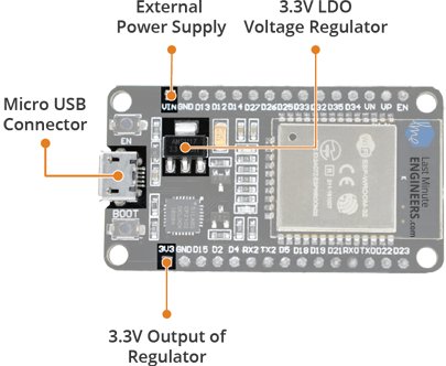
Power to the ESP32 development board is supplied via the on-board MicroB USB connector. Alternatively, if you have a regulated 5V voltage source, the VIN pin can be used to directly supply the ESP32 and its peripherals.
Also the sleep current of the ESP32 chip is less than 5 µA, making it suitable for battery powered and wearable electronics applications.
Warning:
The ESP32 requires a 3.3V power supply and 3.3V logic levels for communication. The GPIO pins are not 5V-tolerant! If you want to interface the board with 5V (or higher) components, you’ll need to do some level shifting.
Relay Pinout
For demonstration purposes, let’s take a look at the pinout of a 2-channel relay module. Using a relay module with a different number of channels is similar.

On the left side, there are two sets of three sockets to connect high voltages, and the pins on the right side (low-voltage) connect to the ESP32 GPIOs.
Mains Voltage Connections
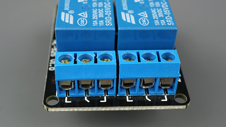
The relay module shown in the previous photo has two connectors, each with three sockets: common (COM), Normally Closed (NC), and Normally Open (NO).
- COM: connect the current you want to control (mains voltage).
- NC (Normally Closed): the normally closed configuration is used when you want the relay to be closed by default. The NC are COM pins are connected, meaning the current is flowing unless you send a signal from the ESP32 to the relay module to open the circuit and stop the current flow.
- NO (Normally Open): the normally open configuration works the other way around: there is no connection between the NO and COM pins, so the circuit is broken unless you send a signal from the ESP32 to close the circuit.
Control Pins
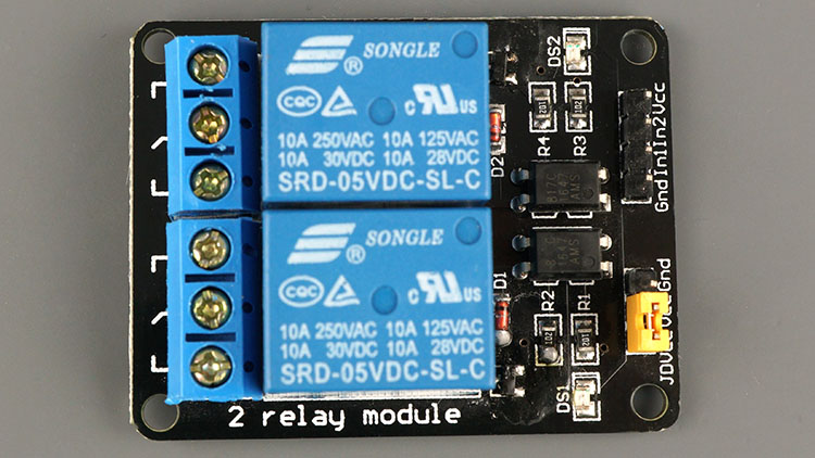
The low-voltage side has a set of four pins and a set of three pins. The first set consists of VCC and GND to power up the module, and input 1 (IN1) and input 2 (IN2) to control the bottom and top relays, respectively.
If your relay module only has one channel, you’ll have just one IN pin. If you have four channels, you’ll have four IN pins, and so on.
The signal you send to the IN pins, determines whether the relay is active or not. The relay is triggered when the input goes below about 2V. This means that you’ll have the following scenarios:
-
Normally Closed configuration (NC):
- HIGH signal – current is flowing
- LOW signal – current is not flowing
-
Normally Open configuration (NO):
- HIGH signal – current is not flowing
- LOW signal – current in flowing
You should use a normally closed configuration when the current should be flowing most of the times, and you only want to stop it occasionally.
Use a normally open configuration when you want the current to flow occasionally (for example, turn on a lamp occasionally).
Power Supply Selection
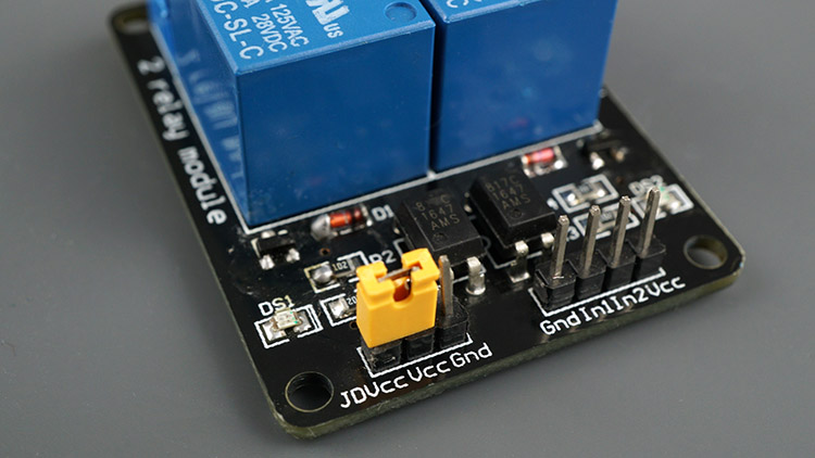
The second set of pins consists of GND, VCC, and JD-VCC pins. The JD-VCC pin powers the electromagnet of the relay. Notice that the module has a jumper cap connecting the VCC and JD-VCC pins; the one shown here is yellow, but yours may be a different color.
With the jumper cap on, the VCC and JD-VCC pins are connected. That means the relay electromagnet is directly powered from the ESP32 power pin, so the relay module and the ESP32 circuits are not physically isolated from each other.
Without the jumper cap, you need to provide an independent power source to power up the relay’s electromagnet through the JD-VCC pin. That configuration physically isolates the relays from the ESP32 with the module’s built-in optocoupler, which prevents damage to the ESP32 in case of electrical spikes.
Basic code for InfluxDB 2
// InfluxDB 2 server url, e.g. http://192.168.1.48:9999 (Use: InfluxDB UI -> Load Data -> Client Libraries)
#define INFLUXDB_URL "influxdb-url"
// InfluxDB 2 server or cloud API authentication token (Use: InfluxDB UI -> Load Data -> Tokens -> <select token>)
#define INFLUXDB_TOKEN "token"
// InfluxDB 2 organization name or id (Use: InfluxDB UI -> Settings -> Profile -> <name under tile> )
#define INFLUXDB_ORG "org"
// InfluxDB 2 bucket name (Use: InfluxDB UI -> Load Data -> Buckets)
#define INFLUXDB_BUCKET "bucket"

// Single InfluxDB instance
InfluxDBClient client(INFLUXDB_URL, INFLUXDB_ORG, INFLUXDB_BUCKET, INFLUXDB_TOKEN);
The next step is adding data. Single data row is represented by the class. It consists of measurement name (like a table name), tags (which labels data) and fields (values to store):
// Define data point with measurement name 'device_status`
Point pointDevice("device_status");
// Set tags
pointDevice.addTag("device", "ESP8266");
pointDevice.addTag("SSID", WiFi.SSID());
// Add data
pointDevice.addField("rssi", WiFi.RSSI());
pointDevice.addField("uptime", millis());
And finally, write data to db:
// Write data
client.writePoint(pointDevice);
Complete source code is available in BasicWrite example.
Peripherals and I/O
Although the ESP32 has total 48 GPIO pins, only 25 of them are broken out to the pin headers on both sides of the development board. These pins can be assigned to all sorts of peripheral duties, including:
- 15 ADC channels – 15 channels of 12-bit SAR ADC’s. The ADC range can be set, in firmware, to either 0-1V, 0-1.4V, 0-2V, or 0-4V
- 2 UART interfaces – 2 UART interfaces. One is used to load code serially. They feature flow control, and support IrDA too!
- 25 PWM outputs – 25 channels of PWM pins for dimming LEDs or controlling motors.
- 2 DAC channels – 8-bit DACs to produce true analog voltages.
- SPI, I2C & I2S interface – There are 3 SPI and 1 I2C interfaces to hook up all sorts of sensors and peripherals, plus two I2S interfaces if you want to add sound to your project.
- 9 Touch Pads – 9 GPIOs feature capacitive touch sensing.
Multiplexed I/Os
- 15 ADC channels
- 2 UART interfaces
- 25 PWM outputs
- 2 DAC channels
- SPI, I2C & I2S interface
- 9 Touch Pads
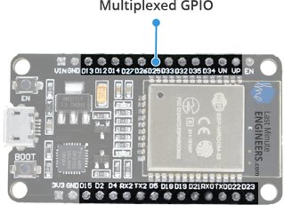
Thanks to the ESP32’s pin multiplexing feature (Multiple peripherals multiplexed on a single GPIO pin). Meaning a single GPIO pin can act as an ADC input/DAC output/Touch pad.
Input Only GPIOs
Pin D34, D35, VP and VN cannot be configured as outputs, but they can be used as either digital inputs, analog inputs, or for other unique purposes. Also note that they do not have internal pull-up or pull-down resistors, like the other GPIO pins.
Also GPIO pins VP and VN are an integral part of the ultra-low-noise pre-amplifier for the ADC, which help to configure the sampling time and noise of the pre-amp.
Начинаем программирование
Как и у любой платы, основанной на ESP32, у MH-ET LIVE ESP32 DevKit есть достаточно большой набор языков программирования. Во-первых, это Arduino C, во-вторых, Lua, а в-третьих и в-четвертых — MicroPython и Espruino. Про Espruino — сборку JS для программирования микроконтроллеров — уже рассказывалось в ][, но в той статье разбиралась работа только на плате Espruino Pico, заточенной под Espruino.
INFO
К сожалению, портирование Espruino на ESP32 еще не до конца завершено. Часть возможностей, например обновление по воздуху и Bluetooth, недоступна. Но так как Espruino — open source проект, любой может добавить свою функциональность.
Установка
-
Скачиваем на официальном сайте свежую сборку Espruino. А если не доверяешь готовым сборкам, то можно собрать прошивку самостоятельно:
-
Несмотря на то что мы будем программировать на JS, для установки все равно нужен Python, а конкретно . Повторяя свою предыдущую статью, скажу, что для его установки, при условии, что уже установлен, достаточно набрать в консоли/терминале: .
- В терминале перейти в папку с прошивкой. Кроме самого файла Espruino, здесь лежат файлы и . Это необходимые компоненты, но в некоторых сборках их может не быть, тогда их придется скачать отсюда.
-
Запускаем процесс прошивки, не забыв изменить порт, указанный в данном примере, на свой, а также при необходимости указать другое имя прошивки. Здесь она называется .
Процесс прошивки
IDE
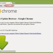
Разработчики Espruino создали свою IDE, . Эта программа распространяется через Chrome Web Store, также существуют нативные приложения для Windows ( и ).
Espruino Web IDE
Перед первым запуском нужно залезть в настройки, вкладка COMMUNICATIONS, и убедиться, что скорость общения выставлена на 115200, а также изменить поле Save on Send с No на Yes, иначе все программы после перезапуска слетят.
Теперь достаточно запустить IDE, подключиться к плате и набрать в консоли : если ты получил , значит, все настроено правильно и можно начинать полноценную работу.
Загрузка …
Hello world
Во всех языках программирования, предназначенных или модифицированных для программирования микроконтроллеров, самая простая программа — так называемый , мигание встроенным светодиодом. Но это как-то скучно. Поэтому нашей первой программой станет программа для управления светодиодом с помощью веб-страницы. И действительно, JS — это же язык веба.
Можно заметить, что синтаксис практически ничем не отличается от обычного JS. Давай разбираться, что же происходит в этой программе.
- — для начала мы подгрузили необходимый нам модуль для работы с Wi-Fi. Логично будет задаться вопросом: а откуда мы его взяли? Допустим, есть встроенные в прошивку модули. А если нам нужно загрузить с какого-нибудь внешнего сайта? Функция поддерживает синтаксис вида , а WebIDE для поиска модулей онлайн, по умолчанию используется .
- Следующий блок кода отвечает за поднятие точки доступа с именем EspruinoAP и паролем 0123456789. В случае успешного запуска в консоль выводится соответствующее сообщение.
- Функция — собственно сам веб-сервер. В этой функции разбирается адрес и проверяется, что нужно сделать, в зависимости от запроса:
- если загружается первая страница — , то вернуть 200-й заголовок и сообщение типа «Hello, ][aker!», в обрамлении HTML-тегов;
- если загружается страница включения — , то вернуть 200-й заголовок и сообщение Enable, а также включить светодиод. Заметим, что используется привычная Arduin’щикам функция ;
- небольшое отличие в случае страницы выключения — , для выключения светодиода используется не функция , а метод ;
- во всех остальных случаях возвращаем ошибку «404 — Page Not Found».
- А последняя строка собственно поднимает сервер, с внутренней функцией , на 80-м порте.
Важно заметить, что мы можем возвращать различный контент: обычный текст, HTML, XML и так далее
Вариант 1. Присоединись к сообществу «Xakep.ru», чтобы читать все материалы на сайте
Членство в сообществе в течение указанного срока откроет тебе доступ ко ВСЕМ материалам «Хакера», увеличит личную накопительную скидку и позволит накапливать профессиональный рейтинг Xakep Score!
Подробнее
Вариант 2. Открой один материал
Заинтересовала статья, но нет возможности стать членом клуба «Xakep.ru»? Тогда этот вариант для тебя!
Обрати внимание: этот способ подходит только для статей, опубликованных более двух месяцев назад.
Я уже участник «Xakep.ru»
ESP32 Development Board Pinout
The ESP32 development board has total 30 pins that interface it to the outside world. The connections are as follows:
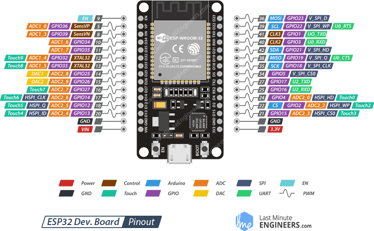
For the sake of simplicity, we will make groups of pins with similar functionalities.
Power Pins There are two power pins viz. VIN pin & 3.3V pin. The VIN pin can be used to directly supply the ESP32 and its peripherals, if you have a regulated 5V voltage source. The 3.3V pin is the output of an on-board voltage regulator. This pin can be used to supply power to external components.
GND is a ground pin of ESP32 development board.
Arduino Pins are nothing but ESP32’s hardware I2C and SPI pins to hook up all sorts of sensors and peripherals in your project.
GPIO Pins ESP32 development board has 25 GPIO pins which can be assigned to various functions programmatically. Each digital enabled GPIO can be configured to internal pull-up or pull-down, or set to high impedance. When configured as an input, it can also be set to edge-trigger or level-trigger to generate CPU interrupts.
ADC Channels The board integrates 12-bit SAR ADCs and supports measurements on 15 channels (analog enabled pins). Some of these pins can be used to build a programmable gain amplifier which is used for the measurement of small analog signals. The ESP32 is also designed to measure the voltages while operating in the sleep mode.
DAC Channels The board features two 8-bit DAC channels to convert digital signals into true analog voltages. This dual DAC can drive other circuits.
Touch Pads The board offers 9 capacitive sensing GPIOs which detect capacitive variations introduced by the GPIO’s direct contact or close proximity with a finger or other objects.
UART Pins ESP32 development board has 2 UART interfaces, i.e. UART0 and UART2, which provide asynchronous communication (RS232 and RS485) and IrDA support, and communicate at up to 5 Mbps. UART provides hardware management of the CTS and RTS signals and software flow control (XON and XOFF) as well.
SPI Pins SPI Pins ESP32 features three SPIs (SPI, HSPI and VSPI) in slave and master modes. These SPIs also support the following general-purpose SPI features:
- 4 timing modes of the SPI format transfer
- Up to 80 MHz and the divided clocks of 80 MHz
- Up to 64-Byte FIFO
All SPIs can also be used to connect to the external Flash/SRAM and LCD.
~ PWM Pins The board has 25 channels (Nearly All GPIO pins) of PWM pins controlled by Pulse Width Modulation (PWM) controller. The PWM output can be used for driving digital motors and LEDs. The controller consists of PWM timers and the PWM operator. Each timer provides timing in synchronous or independent form, and each PWM operator generates the waveform for one PWM channel.
EN Pin is used to enable ESP32. The chip is enabled when pulled HIGH. When pulled LOW the chip works at minimum power.
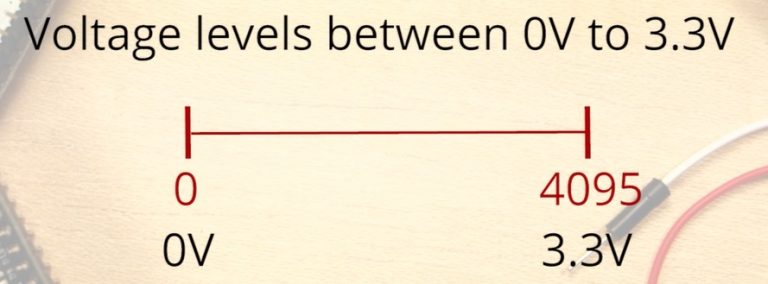
Analog Inputs (ADC)
Reading an analog value with the ESP32 means you can measure varying voltage levels between 0 V and 3.3 V.
The voltage measured is then assigned to a value between 0 and 4095, in which 0 V corresponds to 0, and 3.3 V corresponds to 4095. Any voltage between 0 V and 3.3 V will be given the corresponding value in between.
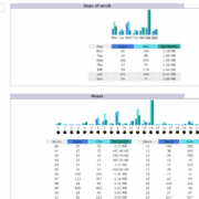
ADC is Non-linear
Ideally, you would expect a linear behavior when using the ESP32 ADC pins. However, that doesn’t happen. What you’ll get is a behavior as shown in the following chart:
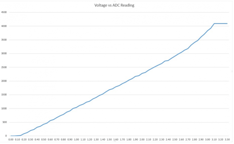
This behavior means that your ESP32 is not able to distinguish 3.3 V from 3.2 V. You’ll get the same value for both voltages: 4095.
The same happens for very low voltage values: for 0 V and 0.1 V you’ll get the same value: 0. You need to keep this in mind when using the ESP32 ADC pins.
There’s a discussion on GitHub about this subject.
Installing the ESP32 Board
To install the ESP32 board in your Arduino IDE, follow these next instructions:
1) Open the preferences window from the Arduino IDE. Go to Arduino > Preferences
2) Enter https://dl.espressif.com/dl/package_esp32_index.json into the “Additional Board Manager URLs” field as shown in the figure below. Then, click the “OK” button:

Note: if you already have the ESP8266 boards URL, you can separate the URLs with a comma as follows:
https://dl.espressif.com/dl/package_esp32_index.json, http://arduino.esp8266.com/stable/package_esp8266com_index.json
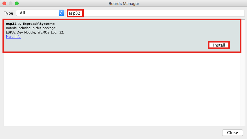
3) Open boards manager. Go to Tools > Board > Boards Manager…

4) Search for ESP32 and press install button for the “ESP32 by Espressif Systems“:
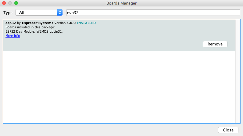
5) That’s it. It should be installed after a few seconds:
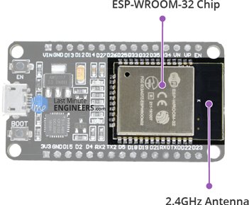
ESP-WROOM-32 Module
The development board equips the ESP-WROOM-32 module containing Tensilica Xtensa Dual-Core 32-bit LX6 microprocessor. This processor is similar to the ESP8266 but has two CPU cores (can be individually controlled), operates at 80 to 240 MHz adjustable clock frequency and performs at up to 600 DMIPS (Dhrystone Million Instructions Per Second).
ESP-WROOM-32 Chip
- Xtensa Dual-Core 32-bit LX6
- Upto 240MHz Clock Freq.
- 520kB internal SRAM
- 4MB external flash
- 802.11b/g/n Wi-Fi transceiver
- Bluetooth 4.2/BLE
There’s also 448 KB of ROM, 520 KB of SRAM and 4MB of Flash memory (for program and data storage) just enough to cope with the large strings that make up web pages, JSON/XML data, and everything we throw at IoT devices nowadays.
The ESP32 Integrates 802.11b/g/n HT40 Wi-Fi transceiver, so it can not only connect to a WiFi network and interact with the Internet, but it can also set up a network of its own, allowing other devices to connect directly to it. The ESP32 supports WiFi Direct as well, which is a good option for peer-to-peer connection without the need of an access point. The WiFi Direct is easier to setup and the data transfer speeds are much better than Bluetooth.
The chip also has dual mode Bluetooth capabilities, meaning it supports both Bluetooth 4.0 (BLE/Bluetooth Smart) and Bluetooth Classic (BT), making it even more versatile.