Mikrotik : чистый ipsec ikev2 между белым и серым ip
Содержание:
Summary
Standards:
L2TP is a secure tunnel protocol for transporting IP traffic using PPP. L2TP encapsulates PPP in virtual lines that run over IP, Frame Relay and other protocols (that are not currently supported by MikroTik RouterOS). L2TP incorporates PPP and MPPE (Microsoft Point to Point Encryption) to make encrypted links. The purpose of this protocol is to allow the Layer 2 and PPP endpoints to reside on different devices interconnected by a packet-switched network. With L2TP, a user has a Layer 2 connection to an access concentrator — LAC (e.g., modem bank, ADSL DSLAM, etc.), and the concentrator then tunnels individual PPP frames to the Network Access Server — NAS. This allows the actual processing of PPP packets to be separated from the termination of the Layer 2 circuit. From the user’s perspective, there is no functional difference between having the L2 circuit terminate in a NAS directly or using L2TP.
It may also be useful to use L2TP just as any other tunneling protocol with or without encryption. The L2TP standard says that the most secure way to encrypt data is using L2TP over IPsec (Note that it is default mode for Microsoft L2TP client) as all L2TP control and data packets for a particular tunnel appear as homogeneous UDP/IP data packets to the IPsec system.
Multilink PPP (MP) is supported in order to provide MRRU (the ability to transmit full-sized 1500 and larger packets) and bridging over PPP links (using Bridge Control Protocol (BCP) that allows to send raw Ethernet frames over PPP links). This way it is possible to setup bridging without EoIP. The bridge should either have an administratively set MAC address or an Ethernet-like interface in it, as PPP links do not have MAC addresses.
L2TP includes PPP authentication and accounting for each L2TP connection. Full authentication and accounting of each connection may be done through a RADIUS client or locally.
MPPE 128bit RC4 encryption is supported.
L2TP traffic uses UDP protocol for both control and data packets. UDP port 1701 is used only for link establishment, further traffic is using any available UDP port (which may or may not be 1701). This means that L2TP can be used with most firewalls and routers (even with NAT) by enabling UDP traffic to be routed through the firewall or router.
L2TP Client
Sub-menu:
Properties
| Property | Description |
|---|---|
| add-default-route (yes | no; Default: no) | Whether to add L2TP remote address as a default route. |
| allow (mschap2 | mschap1 | chap | pap; Default: mschap2, mschap1, chap, pap) | Allowed authentication methods. |
| connect-to (IP; Default: ) | Remote address of L2TP server |
| comment (string; Default: ) | Short description of the tunnel. |
| default-route-distance (byte; Default: ) | Since v6.2, sets distance value applied to auto created default route, if add-default-route is also selected |
| dial-on-demand (yes | no; Default: no) | connects only when outbound traffic is generated. If selected, then route with gateway address from 10.112.112.0/24 network will be added while connection is not established. |
| disabled (yes | no; Default: yes) | Enables/disables tunnel. |
| keepalive-timeout (integer ; Default: 60s) | Since v6.0rc13, tunnel keepalive timeout in seconds. |
| max-mru (integer; Default: 1460) | Maximum Receive Unit. Max packet size that L2TP interface will be able to receive without packet fragmentation. |
| max-mtu (integer; Default: 1460) | Maximum Transmission Unit. Max packet size that L2TP interface will be able to send without packet fragmentation. |
| mrru (disabled | integer; Default: disabled) | Maximum packet size that can be received on the link. If a packet is bigger than tunnel MTU, it will be split into multiple packets, allowing full size IP or Ethernet packets to be sent over the tunnel. |
| name (string; Default: ) | Descriptive name of the interface. |
| password (string; Default: «») | Password used for authentication. |
| profile (name; Default: default-encryption) | Used . |
| user (string; Default: ) | User name used for authentication. |
| use-ipsec (yes | no; Default: no) | When this option is enabled, dynamic IPSec peer configuration and policy is added to encapsulate L2TP connection into IPSec tunnel. |
| ipsec-secret (string; Default: ) | Preshared key used when use-ipsec is enabled. |
Quick example
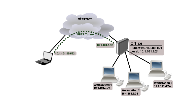
This example demonstrates how to set up L2TP client with username «l2tp-hm», password «123» and server 10.1.101.100
 /interface l2tp-client>add name=l2tp-hm user=l2tp-hm password=123 \
\... connect-to=10.1.101.100 disabled=no
 /interface l2tp-client> print detail
Flags: X - disabled, R - running
 0    name="l2tp-hm" max-mtu=1460 max-mru=1460 mrru=disabled
      connect-to=10.1.101.100 user="l2tp-hm" password="123"
      profile=default-encryption add-default-route=no dial-on-demand=no
      allow=pap,chap,mschap1,mschap2
Summary
While other IPsec howtos fully describe how to set a secure tunnel to get traffic in between two networks, but none of them describe how to get traffic to go over a tunnel where the destination isn’t a network on the remote end
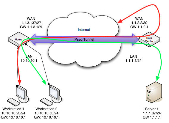
In our scenario we’ll assume a public network at a datacenter, which has public IPs, and a home network connected via a single static IP
The datacenter network is 1.1.1.0/24 It connects to the internet via ISP1 which has a gateway of 1.1.2.1/30 and an IP on the WAN interface of 1.1.2.2/30. ISP1 is statically routing 1.1.1.0/24 to 1.1.2.2
At the home we have a network 10.10.10.0/24 and public IP of 1.1.3.130/27 on the WAN
Now the goal is to not only have traffic destined between 10.10.10.0/24 and 1.1.1.1/24 to flow over the IPsec tunnel encrypted, but we want all the traffic sourced from 10.10.10.0/24 destined for 0.0.0.0/0 to flow over the IPsec tunnel route out gateway of the datacenter network. (1.1.2.1).
IP Connectivity
On both routers ether1 is used as wan port and ether2 is used for LAN. Also NAT rule is set to masquerade the private network at the home.
On the home router:
   /ip address
   add address=1.1.3.137/27 interface=ether1
   add address=10.10.10.1/24 interface=ether2
   /ip route
   add gateway=1.1.3.129
   /ip firewall nat
   add chain=srcnat out-interface=ether1 action=masquerade
On the datacenter router:
   /ip address
   add address=1.1.2.2/30 interface=ether1
   add address=1.1.1.1/24 interface=ether2
   /ip route
   add gateway=1.1.2.1
IPsec Peer’s config
Next step is to add peer’s configuration. We need to specify peers address and port and pre-shared-key. Other parameters are left to default values.
Home router:
/ip IPsec peer add address=1.1.2.2/32:500 auth-method=pre-shared-key secret="test"
Datacenter router:
/ip IPsec peer add address=1.1.3.137/32:500 auth-method=pre-shared-key secret="test"
Policy and proposal
It is important that proposed authentication and encryption algorithms match on both routers. In this example we can use predefined «default» proposal
    /ip IPsec proposal> print  Flags: X - disabled   0   name="default"
   auth-algorithms=sha1 enc-algorithms=3des lifetime=30m
   pfs-group=modp1024
As we already have proposal as a next step we need correct IPsec policy. We want to encrypt traffic coming form 1.1.1.0/24 to 10.10.10.0/24 and vice versa.
Home router:
   /ip IPsec policy add src-address=10.10.10.0/24:any dst-address=1.1.1.0/24:any \
   sa-src-address=1.1.3.137 sa-dst-address=1.1.2.2 \
   tunnel=yes action=encrypt proposal=default
Datacenter router:
   /ip IPsec policy add src-address=1.1.1.0/24:any dst-address=10.10.10.0/24:any \
   sa-src-address=1.1.2.2 sa-dst-address=1.1.3.137 \
   tunnel=yes action=encrypt proposal=default
Note that we configured tunnel mode instead of transport, as this is site to site encryption.
NAT Bypass
At this point if you will try to establish IPsec tunnel it will not work, packets will be rejected. This is because the home router has a NAT rule that is changing source address after packet is encrypted. Datacenter router receives encrypted packet but is unable to decrypt it because source address do not match address specified in policy configuration.
To fix this we need to set up NAT bypass rule.
Home router:
   /ip firewall nat add chain=srcnat action=accept  place-before=0 \
   src-address=10.10.10.0/24 dst-address=1.1.1.0/24
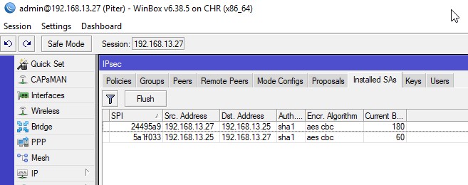
Monitoring
Monitor command can be used to monitor status of the tunnel on both client and server.
 /interface l2tp-client> monitor 0
     status: "connected"
     uptime: 7h24m18s
  idle-time: 6h21m4s
   encoding: "MPPE128 stateless"
        mtu: 1450
        mru: 1450
Read-only properties
| Property | Description |
|---|---|
| status () | Current L2TP status. Value other than «connected» indicates that there are some problems establishing tunnel.
|
| uptime (time) | Elapsed time since tunnel was established. |
| idle-time (time) | Elapsed time since last activity on the tunnel. |
| encoding () | Used encryption method |
| local-address (IP Address) | IP Address of local interface |
| remote-address (IP Address) | IP Address of remote interface |
| mru (integer) | Negotiated and used MRU |
Настройка интернета для VPN клиентов L2TP в MikroTik
ЭþàòþÿÃÂþàñÃÂôõàòÃÂýõÃÂõý ÷ð ÃÂðüúø ôðýýþù ÃÂÃÂðÃÂÃÂø, ÃÂ.ú. þÃÂýþÃÂøÃÂÃÂààôþÿþûýøÃÂõûÃÂýÃÂü ÃÂõÃÂòøÃÂðü ôûàVPN úûøõýÃÂþò. âðúøàÃÂõÃÂòøÃÂþò üþöõàñÃÂÃÂàüýþöõÃÂÃÂòþ ø òÃÂõ þýø øüõÃÂàøýôøòøôÃÂðûÃÂýÃÂàÃÂðÃÂðúÃÂõÃÂ(ôûàÃÂõàúÃÂþ øÃÂõÃÂ: ýÃÂöýþ ýðÃÂÃÂÃÂþøÃÂàø ÃÂð÷ÃÂõÃÂøÃÂàDNS ÷ðÿÃÂþÃÂàø Masquerade).
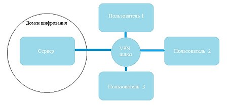
àÃÂÃÂþù ýðÃÂÃÂÃÂþùúõ ñÃÂôÃÂàÃÂÃÂðÃÂÃÂòþòðÃÂàôòð ÃÂþÃÂÃÂõÃÂð MikroTik, þôøý ò úðÃÂõÃÂÃÂòð ÃÂõÃÂòõÃÂð, ôÃÂÃÂóþù ò úðÃÂõÃÂÃÂòõ úûøõýÃÂð. ÃÂð ÃÂÃÂðÿõ ÃÂþ÷ôðýøõ ÃÂðúþóþ ÿþôúûÃÂÃÂõýøàÃÂÃÂþøàþñÃÂðÃÂøÃÂàòýøüðýøõ ýð üþôõûàMikroTik, ÃÂ.ú. þàýõà÷ðòøÃÂøàúþûøÃÂõÃÂÃÂòþ VPN ÿþôúûÃÂÃÂõýøù, ð ÃÂðúöõ òþ÷üþöýþÃÂÃÂàþñÃÂðñðÃÂÃÂòðÃÂàÃÂðúøõ ÿþÃÂþúø ôðýýÃÂÃÂ. ÃÂûàúþýÃÂÃÂûÃÂÃÂðÃÂøø ÿþ ÃÂÃÂþüàòþÿÃÂþÃÂàþñÃÂðÃÂðùÃÂõÃÂàò ÃÂðÃÂÃÂÃÂþùúð-ÃÂøúÃÂþÃÂøú.ÃÂúÃÂàÃÂõÃÂõ÷ úþýÃÂðúÃÂýÃÂàÃÂþÃÂüÃÂ.
ÃÂûàþñÃÂõôøýõýøàôòÃÂàþÃÂøÃÂþò ø ÃÂðñþÃÂàüðÃÂÃÂÃÂÃÂÃÂø÷ðÃÂøø ôðýýÃÂàýðÃÂÃÂÃÂþùúàûÃÂÃÂÃÂõ ÃÂð÷ñøÃÂàýð ôòð ñûþúð:
- ÃÂðÃÂÃÂÃÂþùúð úûøõýÃÂ-ÃÂõÃÂòõÃÂýþù ÃÂðÃÂÃÂø;
- ÃÂþñðòûõýøõ ÃÂÃÂðÃÂøÃÂõÃÂúøàüðÃÂÃÂÃÂÃÂÃÂþò ôûàÿÃÂþÃÂþöôõýøàÃÂÃÂðÃÂøúð.
áõÃÂòõÃÂýðàÃÂðÃÂÃÂàñÃÂûð þÿøÃÂðýð òðÃÂõ, ýþ ÃÂÃÂõñÃÂõàúþÃÂÃÂõúÃÂøÃÂþòúø ò òøôõ ÃÂÃÂðÃÂøÃÂõÃÂúøàðôÃÂõÃÂþò ôûàVPN úûøõýÃÂð
ÃÂðÃÂÃÂÃÂþùúð ýðÃÂþôøÃÂÃÂàPPP->Interface->Secrets
/ppp secret
add local-address=192.168.10.1 name=user2 password=user2 profile=l2tp \
remote-address=192.168.10.2
ð úûøõýÃÂÃÂúðàÃÂðÃÂÃÂàÃÂþÃÂÃÂþøàø÷ ýðÃÂÃÂÃÂþùúø L2TP úûøõýÃÂð.
ÃÂðÃÂÃÂÃÂþùúð ýðÃÂþôøÃÂÃÂàPPP->Interface->+L2TP Client
/interface l2tp-client
add connect-to=90.200.100.99 disabled=no ipsec-secret=TopNet_Pass use-ipsec=yes name=\
l2tp-out1 password=user2 user=user2
ÃÂÃÂþ ÿÃÂðòøûþ ÃÂúðöõàÃÂþÃÂÃÂõÃÂàMikroTik úÃÂôð ýðÿÃÂðòûÃÂÃÂàÃÂÃÂðÃÂøú.
ÃÂðÃÂÃÂÃÂþùúð ýðÃÂþôøÃÂÃÂàIP->Routes
/ip route
add distance=1 dst-address=192.168.88.0/24 gateway=192.168.10.2
ÃÂðÃÂÃÂÃÂþùúð ýðÃÂþôøÃÂÃÂàIP->Routes
/ip route
add distance=1 dst-address=192.168.0.0/24 gateway=192.168.10.1
áþ÷ôðýøõ VPN ÿþôúûÃÂÃÂõýøàL2TP Windows
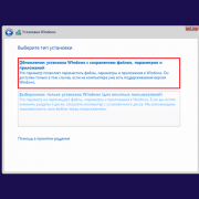
ÃÂá ÃÂõüõùÃÂÃÂòð Windows øüõÃÂàÃÂÃÂðÃÂýÃÂù VPN úûøõýÃÂ, úþÃÂþÃÂÃÂù þÃÂûøÃÂýþ ÿþôÃÂþôøàÿþô ÃÂÃÂàÃÂþûÃÂ. ÃÂûàõóþ ýðÃÂÃÂÃÂþùúø ýÃÂöýþ ÿõÃÂõùÃÂø
ÃÂðýõûàÃÂÿÃÂðòûõýøÃÂ\áõÃÂàø ÃÂýÃÂõÃÂýõÃÂ\æõýÃÂàÃÂÿÃÂðòûõýøàÃÂõÃÂÃÂüø ø þñÃÂøü ôþÃÂÃÂÃÂÿþü
Настройка
Настройка маршрутизатора
Через графический интерфейс
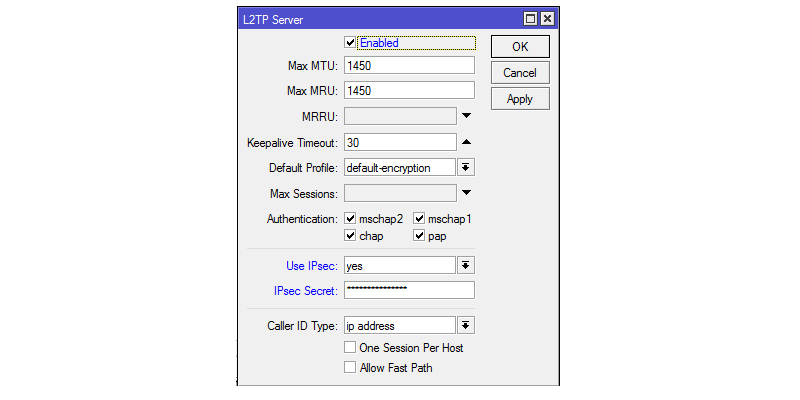
Включить L2TP-сервер. Не смотря на то, что L2TP не несет в себе нормального шифрования, лучше оставить только аутентификацию «mschap2» как наиболее надежную.

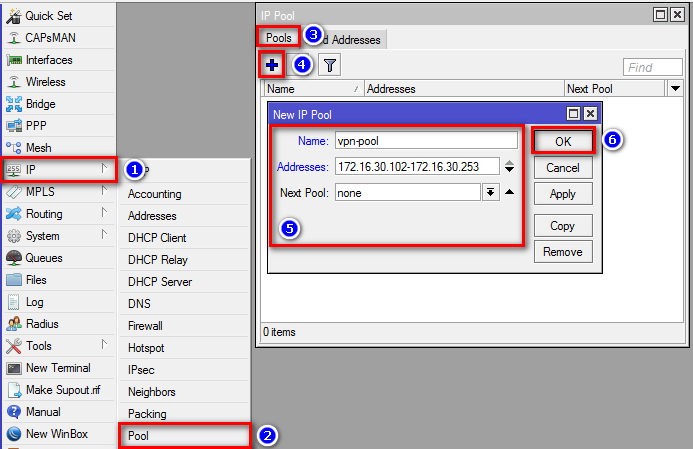
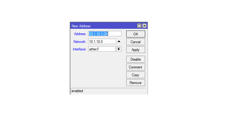
Создать пул адресов для VPN-подключений:
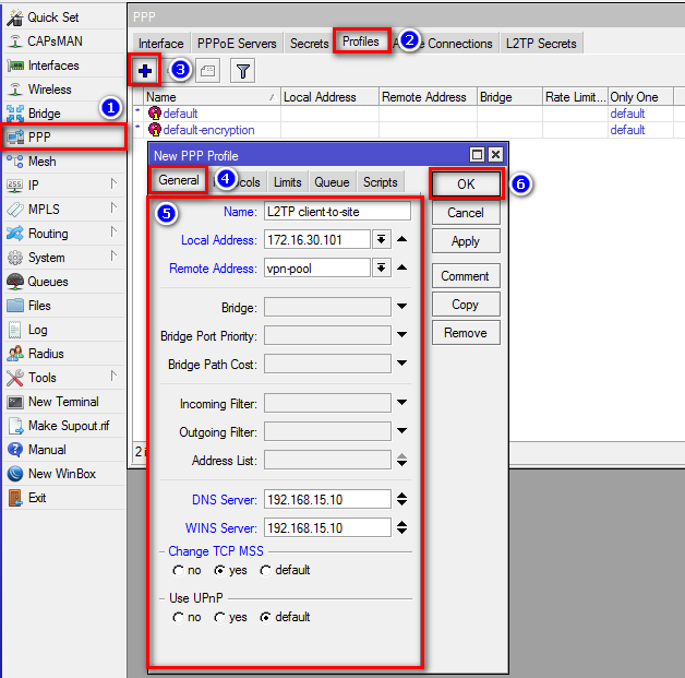
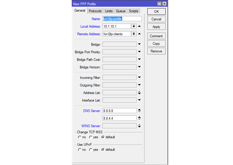
Создать профиль для VPN подключений. Указать адрес сервера DC1, который является DNS и WINS сервером. Без указания DNS и WINS VPN-подключение произойдет, но не будет возможности обращаться к узлам по именам.
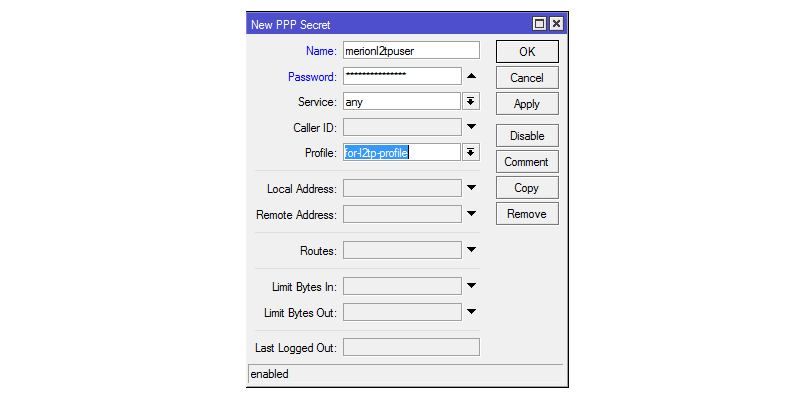
Добавить аккаунт пользователя:
На интерфейсе маршрутизатора, который смотрит в локальную сеть включить arp-proxy. Это нужно для того, чтобы удаленный клиент мог связываться с локальными хостами: 
Создать профиль IPSec для подключения клиента (адрес 0.0.0.0/0 т.к. удаленный адрес клиента неизвестен): 
Через консоль
/interface l2tp-server server set authentication=mschap2 enabled=yes
/ip pool add name=vpn-pool ranges=172.16.30.102-172.16.30.253
/ppp profile add name=»L2TP client-to-site» change-tcp-mss=yes local-address=172.16.30.101 remote-address=vpn-pool dns-server=192.168.15.10 wins-server=192.168.15.10
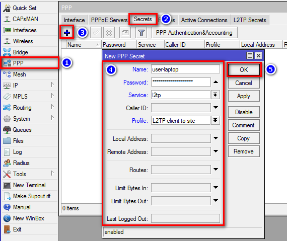
/ppp secret add name=user-laptop password=user-laptop-password profile=»L2TP client-to-site» service=l2tp
/interface ethernet set ether1-LAN1 arp=proxy-arp
/ip ipsec peer add address=0.0.0.0/0 comment=client-to-site enc-algorithm=3des,aes-128,aes-256 exchange-mode=main-l2tp generate-policy=port-strict nat-traversal=yes secret=ipsec-password send-initial-contact=no auth-method=pre-shared-key
- AES является единственным алгоритмом, который поддерживается модулем аппаратного шифрования, если такой установлен на маршрутизатор.
- Если требуется подключение только по L2TP без IPsec, то достаточно пропустить последний пункт по настройке IPsec. При этом надо учесть, что встроенный VPN-клиент Windows не поддерживает подключение по L2TP без IPSec. Для того, чтобы такое подключение заработало необходимо править реестр операционной системы.
Summary
Sub-menu:
Standards:
GRE (Generic Routing Encapsulation) is a tunnelling protocol that was originally developed by Cisco. It can encapsulate a wide variety of protocols creating a virtual point-to-point link.
GRE is the same as IPIP and EoIP which were originally developed as stateless tunnels. Which means that if the remote end of the tunnel goes down, all traffic that was routed over the tunnels will gets blackholed. To solve this problem, RouterOS have added ‘keepalive’ feature for GRE tunnels.
GRE tunnel adds a 24 byte overhead (4-byte gre header + 20-byte IP header).
Note: GRE tunnel can forward only IP and IPv6 packets (ethernet type 800 and 86dd). Do not use «Check gateway» option «arp» when GRE tunnel is used as route gateway.
Туннель EoIP
Теперь нам надо создать туннель между нашими устройствами. Делается это также просто.
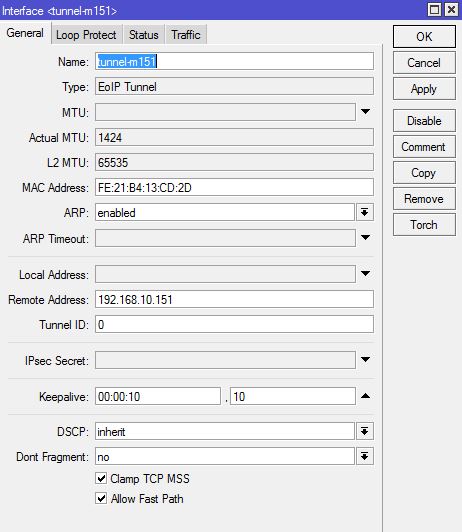
MikroTik M151-office
#
#
> interface eoip
/interface eoip> add name=tunnel-m152 tunnel-id=0 remote-address=192.168.10.152
|
1 |
admin@M151-office>interfaceeoip admin@M151-officeinterfaceeoip>add name=tunnel-m152 tunnel-id=remote-address=192.168.10.152 |
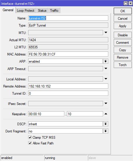
MikroTik M152-remote1
#
#
> interface eoip
/interface eoip> add name=tunnel-m151 tunnel-id=0 remote-address=192.168.10.151
|
1 |
admin@M152-remote1>interfaceeoip admin@M152-remote1interfaceeoip>add name=tunnel-m151 tunnel-id=remote-address=192.168.10.151 |
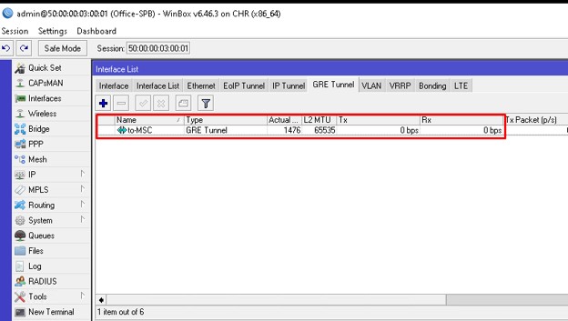
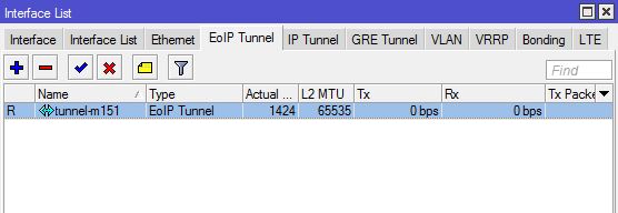
О работоспособности туннеля нам скажет буква R (running).
В консоли:
#
#
> interface eoip print
Flags: X — disabled, R — running
0 R name=»tunnel-m151″ mtu=auto actual-mtu=1424 l2mtu=65535 mac-address=FE:21:B4:13:CD:2D arp=enabled arp-timeout=auto
loop-protect=default loop-protect-status=off loop-protect-send-interval=5s loop-protect-disable-time=5m
local-address=0.0.0.0 remote-address=192.168.10.151 tunnel-id=0 keepalive=10s,10 dscp=inherit clamp-tcp-mss=yes
dont-fragment=no allow-fast-path=yes
>
|
1 |
admin@M152-remote1>interfaceeoip print FlagsX-disabled,R-running Rname=»tunnel-m151″mtu=auto actual-mtu=1424l2mtu=65535mac-address=FE21B413CD2Darp=enabled arp-timeout=auto loop-protect=defaultloop-protect-status=off loop-protect-send-interval=5sloop-protect-disable-time=5m local-address=0.0.0.0remote-address=192.168.10.151tunnel-id=keepalive=10s,10dscp=inherit clamp-tcp-mss=yes dont-fragment=no allow-fast-path=yes admin@M152-remote1> |
В winbox:
Если вам такой проверки недостаточно, то можете присвоить туннельным интерфейсам на обоих роутерах адреса одной подсети и попинговать.
Настройка L2TP сервера на Mikrotik
VPN для Микротик
2 минуты чтения
В сегодняшней статье расскажем про способ настройки IPsec сервера на Mikrotik, который будет особенно актуален для пользователей MacOS и iOS — L2TP
Дело в том, что в старших релизах iOS и macOS, компания Apple убрала поддержку PPTP из-за уязвимостей безопасности данного протокола. Поэтому, если раньше вы использовали PPTP для подключения к ресурсам локальной сети, то начиная с версий macOS 10.12 и iOS 10 этого сделать не получится.
Настройка
Итак, давайте перейдём к настройке. В нашем случае используется роутер RB951Ui-2HnD и RouterOS версии 6.23. Для настройки будем пользоваться утилитой WinBox последней версии.
Для начала назначим IP адресацию для VPN сети:
Теперь необходимо включить и настроить L2TP сервер, для этого в меню WinBox слева открываем PPP → L2TP Server, включаем сервер, отметив галочкой Enabled, выбираем Use IPsec и задаём пароль:
Далее нужно создать пул адресов, который будет назначаться пользователям, которые будут подключаться к нашему серверу. Вы также можете назначить IP адреса вручную, однако, если пользователей будет много, рекомендуется всё же создать пул. Для этого открываем IP → Pool и создаём новый пул.

Создадим профиль для пользователей, которые будут подключаться к нашему серверу, в котором укажем ранее созданный пул назначаемых адресов. Для этого открываем PPP → Profile → + и добавляем новый профиль, в котором указываем пул, адреса из которого нужно назначать и DNS серверы:
Теперь создадим учётную запись для пользователей, которые будут подключаться к нашему серверу и укажем в ней ранее созданный профиль. Для этого открываем PPP → Secret → + и заполняем следующие поля:
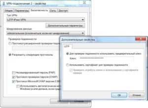
Осталось создать IPsec Peer для L2TP и можно подключаться к нашему новому серверу. Для этого открываем IP → IPsec → Peers → + и заполняем поля следующим образом:

Поля во вкладках Advanced и Encryption можно оставить по умолчанию.
Пожалуйста, расскажите почему?
Нам жаль, что статья не была полезна для вас Пожалуйста, если не затруднит, укажите по какой причине? Мы будем очень благодарны за подробный ответ. Спасибо, что помогаете нам стать лучше!
Подпишитесь на нашу еженедельную рассылку, и мы будем присылать самые интересные публикации Просто оставьте свои данные в форме ниже.
Иногда кажется, что создатели Mikrotik намеренно лишают себя прибыли, не создавая однозначных пошаговых руководств по настройке своих детищ. Почти 100% потребителей этих роутеров пытаются настроить VPN, использовать два или более WAN одновременно или в качестве резервных. Именно это ищут по всей сети (и часто вне рунета) счастливые владельцы этих замечательных устройств. Представьте, на сколько бы увеличилась армия владельцев, если бы для настройки этих функций было два-три визарда в веб-интерфейсе. А сейчас.. сейчас именно благодаря сложности настройки (и, соотв., меньшему количеству желающих купить) мы имеем недорогое, малокапризное для несложных задач устройство, которое надо заставить работать 24х7х365. Например, в качестве VPN-сервера. Поехали!
Протокол L2TP обеспечивает канал передачи данных, туннель.
IPSec обеспечивает защиту данных от просмотра.
Настраивать мы будем тоже по частям – сначала туннель, потом – защита данных.
Итак, имеем роутер Mikrotik с прошивкой 6.30 (июль 2015) c LAN 192.168.88.0/24 (сеть по-умолчанию). WAN не важен, например, 1.2.3.4.
L2TP-соединение – что это такое? Как настроить L2TP-соединение
Сегодня подключения к интернету по локальной или виртуальной сети на основе беспроводных технологий стали очень популярными и среди обычных пользователей, и среди корпоративных клиентов.
Неудивительно, ведь при установке такого защищенного соединения обеспечивается наилучшая защита передаваемых и принимаемых данных, а проще говоря, исходящего и входящего трафика. Одним из самых распространенных типов можно назвать использование протокола L2TP-соединения.
Что это такое и как настроить соединение на его основе самостоятельно, далее и предлагается разобраться.
Принципиально ничего такого, что бы отличалось от создания обычного подключения на основе беспроводных технологий, тут нет, однако многие специалисты советуют соблюсти несколько условий и принять к сведению некоторые рекомендации, чтобы избежать типичных ошибок.
Для начала рассмотрим, что собой представляет данный тип подключения к интернету или по сети с использованием именно такого типа доступа. На самом деле протокол L2TP является одной из разновидностей установки доступа в интернет на основе VPN с применением так называемого туннелирования.
При подключении компьютеров к интернету таким способом обеспечивается максимально возможная конфиденциальность.
И достигается это не только потому, что доступ к туннелю блокируется, но и потому, что все данные на входе и на выходе шифруются. Плюс ко всему – наличие проверочных ключей с обеих сторон.
Иными словами, не зная автоматически генерируемых ключей, украсть или просмотреть информацию никто не может. К тому же, как уже понятно, она находится в зашифрованном виде.
Но это были всего лишь краткие теоретические сведения, так сказать, для общего развития. Теперь перейдем к практическим действиям и рассмотрим использование L2TP-соединения. Что это за технология, думается, немного понятно, так что основные действия по созданию такого подключения от стандартной настройки VPN практически ничем отличаться не будут.
Однако перед тем, как заниматься подобными действиями, обратите внимание на несколько обязательных пунктов, без соблюдения которых создаваемое подключение не то что работать не будет, его даже создать не получится. Основные критерии таковы:
- операционная система не ниже Windows Vista (рекомендуется), хотя в XP настройка тоже возможна;
- наличие адреса корпоративного сервера, к которому предполагается произвести подключение;
- наличие логина и пароля для входа в сеть.